
Radial-reverse combined extrusion molding method for thin-walled cylindrical piece with outer bosses

A technology of extrusion forming and thin-walled tubes, which is applied in the direction of metal extrusion dies, etc., can solve problems such as complex procedures, low strength, and low dimensional accuracy, and achieve the effects of expanding application range, improving production efficiency, and improving mechanical properties

Active Publication Date: 2020-01-17
ZHONGBEI UNIV
View PDF11 Cites 12 Cited by
  • Summary
  • Abstract
  • Description
  • Claims
  • Application Information

AI Technical Summary

Problems solved by technology

At present, this type of component is traditionally processed by casting and welding, which mainly has the following shortcomings: 1. The casting is prone to defects such as shrinkage and porosity, and the strength is low; 2. The strength of the welding part of the welded structure is low and easy to be damaged, and it is easy to be damaged in a special environment. Corrosion; 3. The traditional extrusion method cannot directly form the outer boss, and the formed ring rib can be cut into the outer boss, but forming the ring rib needs multiple times of material gathering, the process is complicated, the dimensional accuracy is low, and the subsequent cutting process will destroy Metal flow lines in key parts
[0006] These mold structures are suitable for the forming of flanges or bosses in the "reverse-radial" process, but there are restrictions on the position and structural size of the flanges or bosses due to the wall thickness of thin-walled cylinders

Method used


Image

  • Radial-reverse combined extrusion molding method for thin-walled cylindrical piece with outer bosses
  • Radial-reverse combined extrusion molding method for thin-walled cylindrical piece with outer bosses
  • Radial-reverse combined extrusion molding method for thin-walled cylindrical piece with outer bosses

Examples


Embodiment Construction

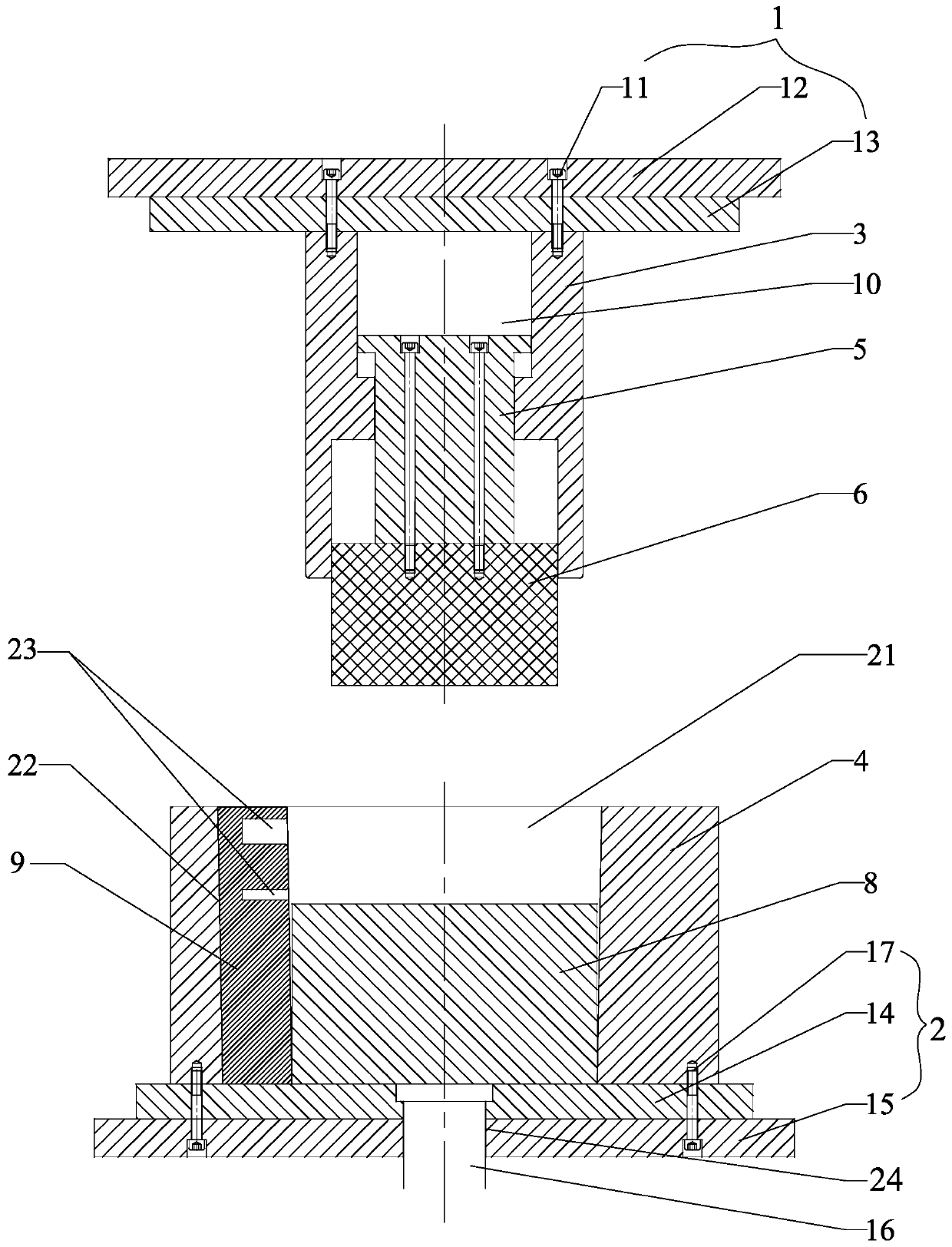
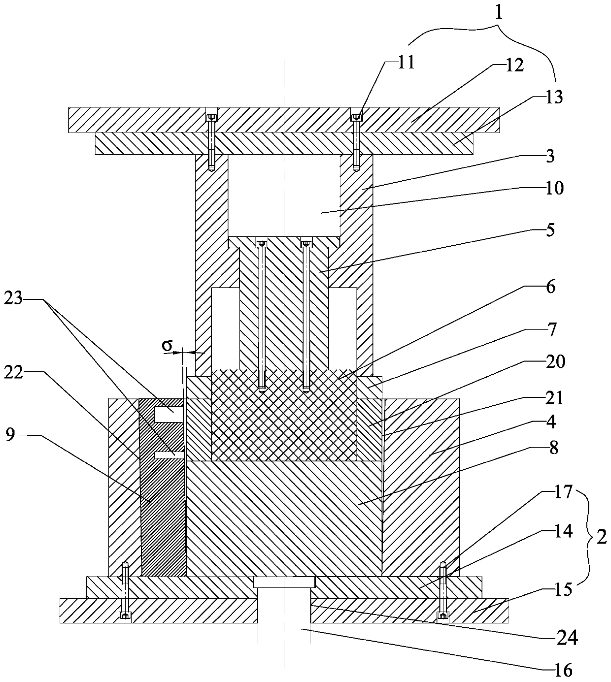
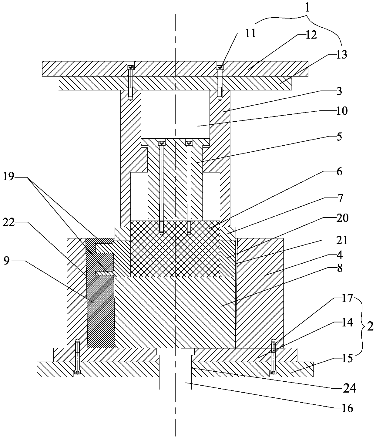
[0030] In order to more clearly illustrate the technical solutions in the embodiments of the present invention or the prior art, the following will briefly introduce the drawings that need to be used in the description of the embodiments or the prior art. Obviously, the accompanying drawings in the following description are only These are some embodiments of the present invention. For those of ordinary skill in the art, other drawings can also be obtained according to these drawings without paying creative labor, such as Figure 1 to Figure 9 shown.

[0031] In the claims, description and above-mentioned drawings of the present invention, unless otherwise clearly defined, the terms "first", "second" or "third" are used to distinguish different objects, not for Describe a specific order.

[0032] In the claims, specification and above-mentioned drawings of the present invention, unless otherwise clearly defined, for orientation words, such as using the terms "center", "transve...


PUM


Abstract

The invention discloses a radial-reverse combined extrusion molding method for a thin-walled cylindrical piece with outer bosses. A radial-reverse combined extrusion mold for the thin-walled cylindrical piece with the outer bosses is related in the method. The mold comprises a male mold, a female mold, a mandrel, a core support, an extrusion ring, a top block and a movable block. The core supportis installed at the bottom of the mandrel. The extrusion ring is connected to the extending outer portion of the core support in a sleeving mode. A cavity and a movable block groove are formed in thefemale mold. The upper portion of the movable block protrudes out of the top block. An inwards-concave boss type cavity is formed in the side face of the top block. The method includes the steps thatthe male mold downwards presses the extrusion ring and a hollow blank, the blank flows in the radial direction to fill in the boss type cavity, then the extrusion ring is omitted, the hollow blank moves down along with the male mold to be extruded into the thin-walled cylindrical piece, the thin-walled cylindrical piece is reversely extruded to rise, the movable block is driven to move up together, and the height of the thin-walled cylindrical piece is increased. By means of the scheme, the thin-walled cylindrical piece with an arbitrary number of bosses with arbitrary sizes at arbitrary positions can be directly formed at a time, and the mechanical performance of the thin-walled cylindrical piece is greatly improved.

Description

technical field [0001] The invention relates to the technical field of plastic processing and forming of metal materials, in particular to a radial-reverse combined extrusion forming method of a thin-walled cylindrical part with an outer boss. Background technique [0002] The main structural feature of thin-walled cylindrical parts with outer bosses is that there are outer raised structures formed on the side walls of hollow cylindrical parts with circular and rectangular cross-sectional shapes. The outer raised structures are called outer bosses, which are often used as bearings. key parts of the force. At present, this type of component is traditionally processed by casting and welding, which mainly has the following shortcomings: 1. The casting is prone to defects such as shrinkage and porosity, and the strength is low; 2. The strength of the welding part of the welded structure is low and easy to be damaged, and it is easy to be damaged in a special environment. Corros...

Claims


Application Information

Patent Timeline
Patent Type & Authority Applications(China)
IPC IPC(8): B21C23/03B21C23/32B21C25/02B21C35/02
CPCB21C23/03B21C23/32B21C25/02B21C35/02
Inventor 王强张治民郭世超于建民张义
Owner ZHONGBEI UNIV
Learn More