Near-field electromagnetic scattering simulation method for super-electric large-size scale target

An electrically large-scale, near-field electromagnetic technology, applied in design optimization/simulation, 3D modeling, image data processing, etc., can solve problems such as difficult to satisfy, save time, simplify the modeling process, and avoid the surface element normal process. Effect

Active Publication Date: 2020-01-17
UNIV OF ELECTRONICS SCI & TECH OF CHINA
View PDF7 Cites 5 Cited by
  • Summary
  • Abstract
  • Description
  • Claims
  • Application Information

AI Technical Summary

Problems solved by technology

[0003] Radar far-field conditions (r>2D 2 / λ, where r represents the distance from the target to the radar, D represents the target size, and λ represents the wavelength of the radar wave) is usually difficult to satisfy

Method used


Image

  • Near-field electromagnetic scattering simulation method for super-electric large-size scale target
  • Near-field electromagnetic scattering simulation method for super-electric large-size scale target
  • Near-field electromagnetic scattering simulation method for super-electric large-size scale target

Examples


Embodiment 1

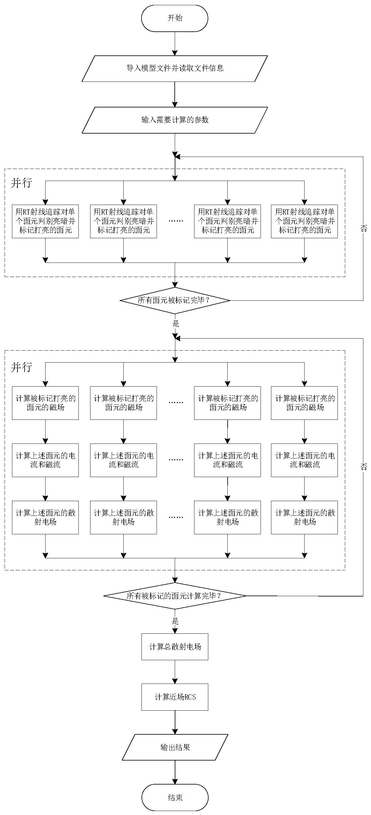
[0048] This embodiment provides a near-field electromagnetic scattering simulation method for ultra-electric large-scale targets, and the specific steps are as follows:

[0049] Step 1: Use the 3D modeling method based on triangular surface element mesh to model, and export it as a model in the general STL (StereoLithography) format for future use.

[0050] Step 2, import the above-mentioned model file in STL format into a Graphics Processing Unit (GPU) for calculation, and read the coordinate information and surface normal information of each triangular surface element constituting the radar target.

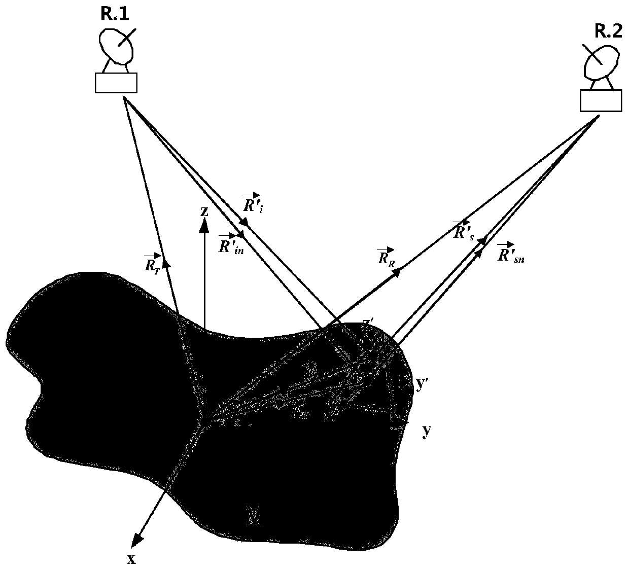
[0051] Step 3, input the parameters to be calculated; the parameters to be calculated include radar system type, radar wave frequency f, incident angle θ, azimuth angle The distance R between the transmitting radar and the center of the target T , the distance R between the receiving radar and the center of the target R , as well as the number of Monte Carlo (MC) simulations ...

Embodiment 2

[0077] The simulation method provided by embodiment 1 is tested: as Figure 4 A cargo ship model is provided with a bounding box of 135m in length, 16m in width and 25m in height, and the following simulation tests are carried out on it: a monostatic radar with a working mode of 300MHz, the incident angle ranges from 45° to 90°, and the azimuth angle ranges from 0 to 360°, the distance from the radar to the target center is r=1km (the simulation result is marked as RCS-1km) and r=10km (the simulation result is marked as RCS-10km).

[0078] Comparison case: the distances from the radar to the target center are r=1km and r=10km respectively, and the conventional far-field scattering simulation test is adopted, and the far-field simulation scattering results are marked as RCS-ff.


PUM


Abstract

The invention discloses a near-field electromagnetic scattering simulation method for a super-electric large-size target. The near-field electromagnetic scattering simulation method comprises the following steps: importing a model file in an STL format, and reading related information of each triangular surface element forming a radar target; inputting parameters needing to be calculated; judgingwhether the surface elements are illuminated by incident waves or not, and marking the illuminated surface elements; calculating the surface current and the magnetic current of each triangular surfaceelement marked to be illuminated: solving a scattering field caused by each triangular surface element marked to be illuminated, solving all scattering fields Esn of the triangular surface elements marked to be illuminated, and adding all the scattering fields Esn according to a vector superposition principle to obtain a total scattering field; according to the following formula, obtaining an RCSvalue sigma0 of the radar target under the near-field situation, and outputting the result. The near-field electromagnetic scattering simulation method fills up the blank in the field of target near-field RCS simulation algorithms, and particularly, electromagnetic simulation processing modes of different surface elements under the near-field scattering condition are more suitable for actual engineering scenes.

Description

technical field [0001] The invention relates to the technical field of electromagnetic scattering, in particular to a near-field electromagnetic scattering simulation method for superelectric large-scale targets. Background technique [0002] In electromagnetic scattering simulation, people often use radar cross section (RCS) to characterize the electromagnetic scattering capability of a target object. It plays an important role in the analysis of target scattering characteristics and identification of air targets, and it is also an important technology to reflect the stealth performance of targets. Therefore, the simulation of RCS has become a key technology in the analysis of radar target electromagnetic scattering characteristics and radar target recognition. [0003] Radar far-field conditions (r>2D 2 / λ, where r represents the distance from the target to the radar, D represents the target size, and λ represents the wavelength of the radar wave) is usually not easy t...

Claims


Application Information

Patent Timeline
Patent Type & Authority Applications(China)
IPC IPC(8): G06F30/20G06T17/20
CPCG06T17/20
Inventor 杨伟廖成晋齐聪慧赵志钦胡皓全雷世文田径
Owner UNIV OF ELECTRONICS SCI & TECH OF CHINA
Why Eureka
Try Eureka