Display structure

A display and photochromic material technology, applied in semiconductor devices, electric solid devices, semiconductor/solid device manufacturing, etc., can solve the problems of reducing display brightness and contrast, and achieve the effect of increasing clarity and improving contrast

Active Publication Date: 2020-01-17
SHENZHEN CHINA STAR OPTOELECTRONICS SEMICON DISPLAY TECH CO LTD
View PDF3 Cites 0 Cited by
  • Summary
  • Abstract
  • Description
  • Claims
  • Application Information

AI Technical Summary

Problems solved by technology

[0007] In view of this, the present invention provides a display structure to solve the problem that the existing display is affected by ambient light (such as under the illumination of strong sunlight), and the reflection of the device in the display will cause a decrease in contrast.
[0008] Furthermore, the present invention provides a display structure to solve the problem in the prior art that the use of polarizers on the light-emitting surface of the display greatly reduces the brightness of the display.

Method used


Image

  • Display structure
  • Display structure
  • Display structure

Examples


Embodiment Construction

[0038] The following descriptions of the various embodiments refer to the accompanying drawings to illustrate specific embodiments in which the present invention can be practiced. Furthermore, the directional terms mentioned in the present invention are, for example, up, down, top, bottom, front, back, left, right, inside, outside, side, surrounding, central, horizontal, transverse, vertical, longitudinal, axial, The radial direction, the uppermost layer or the lowermost layer, etc. are only directions referring to the attached drawings. Therefore, the directional terms used are used to illustrate and understand the present invention, but not to limit the present invention.

[0039] As those skilled in the art would realize, the described embodiments may be modified in various different ways, all without departing from the spirit or scope of the present invention.

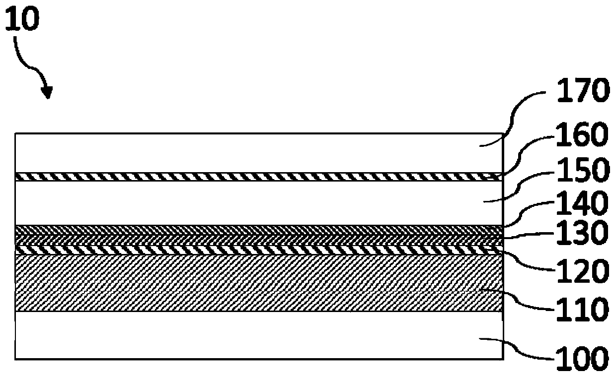
[0040] Please refer to figure 1 As shown, the embodiment of the present invention provides a display structure...


PUM

PropertyMeasurementUnit
thicknessaaaaaaaaaa
thicknessaaaaaaaaaa
thicknessaaaaaaaaaa

Abstract

The invention discloses a display structure. The display structure comprises a transparent anode electrode layer; a reflecting layer arranged on the transparent anode electrode layer; a photochromic material layer arranged on the reflecting layer; and a transparent cathode electrode layer arranged on the photochromic material layer. When the display structure is under the external ambient light, after the external ambient light is reflected by the reflecting layer, the external ambient light is absorbed by the photochromic material layer. According to the invention, the photosensitive photochromic material is added between the electrodes of a display, so that a polaroid is not needed, the brightness of the display is greatly improved, the input energy consumption is reduced, and the service life of the display is prolonged.

Description

technical field [0001] The present invention relates to a display structure, in particular to a display structure for improving luminous efficiency. Background technique [0002] In recent years, liquid crystal displays have become the mainstream of displays. Contrast is a critical parameter for display technology. The impact of contrast on visual effects is very important. Generally speaking, the higher the contrast, the clearer and more eye-catching the image, and the brighter the color; while the lower the contrast, the whole display screen will appear gray. High contrast is very helpful for image clarity, detail performance, and gray level performance. Therefore, how to improve the contrast of display devices is a direction that those skilled in the art are working on. [0003] For liquid crystal display technology, the existing imaging technology must rely on polarized light. The front and rear of the existing liquid crystal display are provided with polarizers attac...

Claims


Application Information

Patent Timeline
Patent Type & Authority Applications(China)
IPC IPC(8): H01L27/32H01L51/52
CPCH10K59/50H10K50/805H10K50/84H10K50/856
Inventor 李文杰
Owner SHENZHEN CHINA STAR OPTOELECTRONICS SEMICON DISPLAY TECH CO LTD
Why Eureka
Try Eureka