Fin type phase change heat dissipation device

A heat dissipation device, finned technology, applied in the field of finned phase change heat dissipation devices, can solve the problems of secondary heat dissipation of the device, failure to absorb heat from heat source, thermal runaway, etc. The structure is simple, the space utilization rate is high, and the effect of increasing heat conduction efficiency

Pending Publication Date: 2020-01-17
GUANGDONG UNIV OF TECH
View PDF0 Cites 2 Cited by
  • Summary
  • Abstract
  • Description
  • Claims
  • Application Information

AI Technical Summary

Problems solved by technology

In addition, when the phase change material is completely phase changed, if the heat cannot be discharged in time, it will not be able to absorb the heat from the heat source, resulting in thermal runaway
The traditional composite phase c

Method used


Image

  • Fin type phase change heat dissipation device
  • Fin type phase change heat dissipation device

Examples


Embodiment

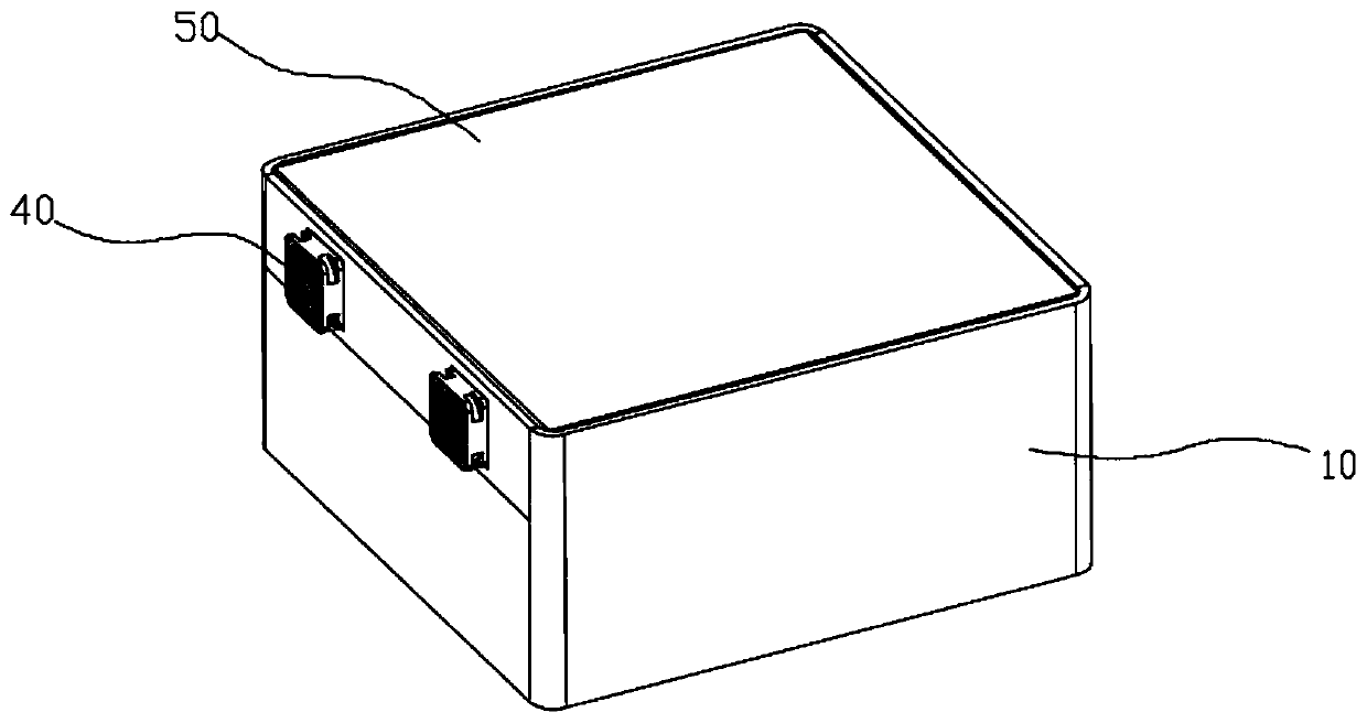
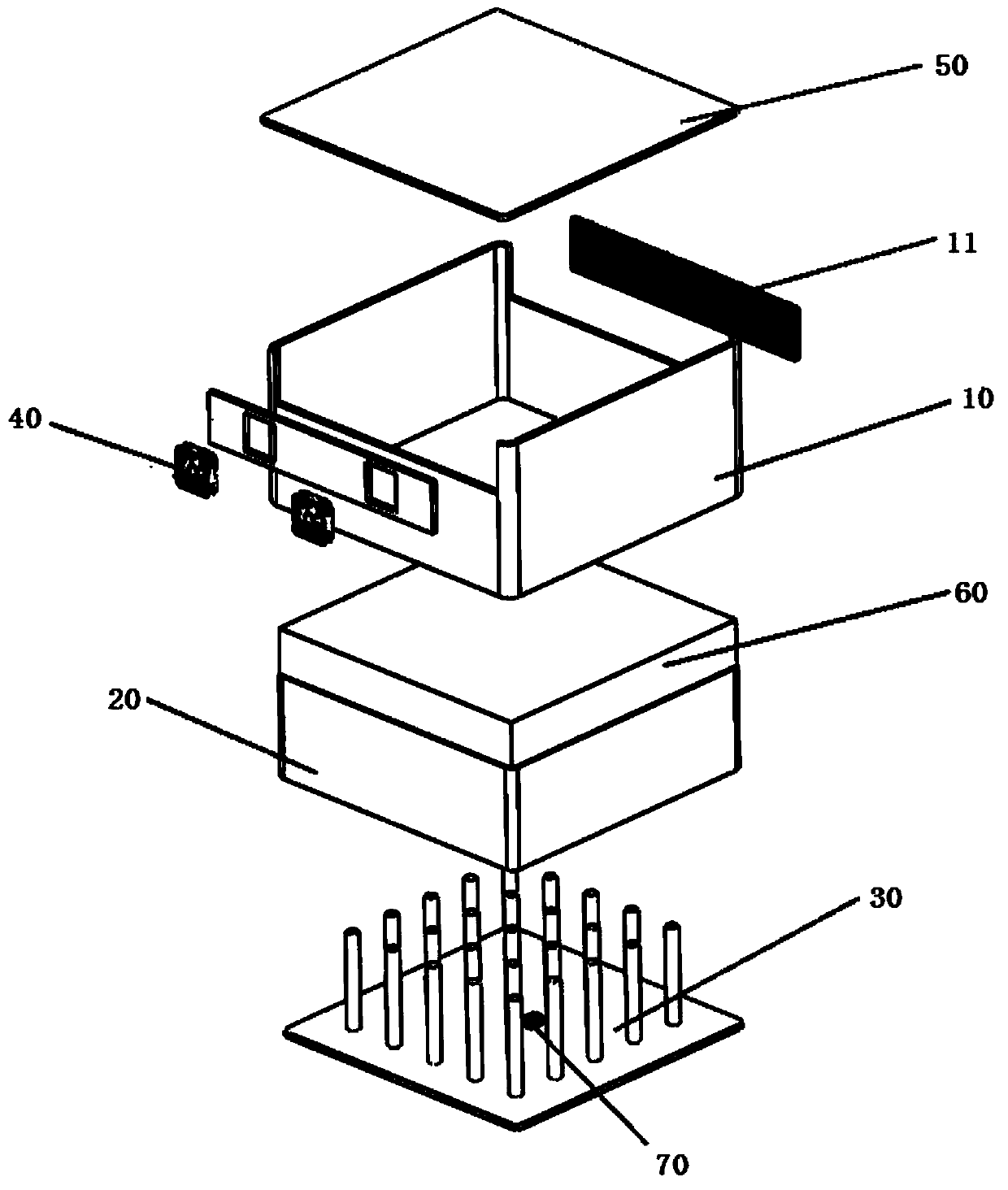
[0025] Please refer to figure 1 with figure 2 , a finned phase change heat dissipation device, comprising a hollow heat dissipation box 10; the heat dissipation box 10 is provided with a metal foam-phase change material composite body 20, and the bottom surface of the metal foam-phase change material composite body 20 is provided with fins Type heat sink 30, the fin of fin type heat sink 30 is inserted in the foam metal-phase change material composite body 10;

[0026] On the side wall of the heat dissipation box 10, an air intake grid 11 is provided above the metal foam-phase change material composite body 20, and an exhaust fan 40 is arranged on the side wall opposite to the air intake grid 11 on the heat dissipation box body 10, and the heat dissipation box body 10 is provided with a top cover 50 .

[0027] As can be seen from the above, when in use, the present invention utilizes the finned heat sink to be in close contact with the heat source to absorb heat, and the ab...


PUM


Abstract

The invention discloses a fin type phase change heat dissipation device which comprises a hollow heat dissipation box body, a foam metal-phase change material complex is arranged in the heat dissipation box body, and a fin type heat sink is arranged on the bottom surface of the foam metal-phase change material complex. Fins of the fin type heat sink are inserted into the foam metal-phase change material complex, an air inlet grid is arranged on the side wall of the heat dissipation box body and is located above the foam metal-phase change material complex, an exhaust fan is arranged on the side wall, opposite to the air inlet grid, of the heat dissipation box body, and the heat dissipation box body is provided with a top cover. The fin type heat sink is beneficial to the rapid conduction of heat of a heat source into a phase change material, so that the heat source is effectively cooled. After the phase-change material is subjected to complete phase change, the heat absorption capacityis greatly reduced, and the heat of the heat source cannot be dissipated, so that the heat stored in the phase-change material needs to be dissipated in time, and the forced convection caused by theexhaust fan can dissipate the heat from the phase-change material rapidly.

Description

technical field [0001] The invention relates to the technical field of heat dissipation, in particular to a finned phase change heat dissipation device. Background technique [0002] With the gradual transition of the communication system to 5G, the communication base station equipment is increasingly developing in the direction of large capacity, high power, and high integration. The heat consumption density of the system is increasing, and the environmental adaptability requirements are getting higher and higher. But smaller and smaller, thermal reliability has gradually become the bottleneck of reliability design. Similarly, a communication base station needs a reasonable heat dissipation system to maintain the normal operation of its internal equipment. [0003] In addition, in recent years, new energy vehicles have become very popular in China due to their unique environmental friendliness. The emergence of lithium-ion batteries more or less meets the requirements for...

Claims


Application Information

Patent Timeline
IPC IPC(8): H01M2/10H01M10/613H01M10/625H01M10/635H01M10/6551H01M10/6563H01M10/659
CPCH01M10/613H01M10/625H01M10/635H01M10/6551H01M10/6563H01M10/659H01M50/20Y02E60/10
Inventor 王长宏曾梓劲
Owner GUANGDONG UNIV OF TECH
Why Eureka
Try Eureka