
Shockproof power distribution cabinet

A technology for power distribution cabinets and outer cabinets, which is applied in the substation/power distribution device casing, anti-seismic equipment, electrical components, etc., and can solve the problems of poor anti-seismic effect, easy generation of electric sparks, high temperature, and ineffective drainage of power distribution cabinets. Achieve the effect of enhancing the anti-seismic effect and reducing the temperature

Active Publication Date: 2020-01-17
SHENZHEN DONGSHENGYUAN ELECTRICAL EQUIP
View PDF5 Cites 2 Cited by
  • Summary
  • Abstract
  • Description
  • Claims
  • Application Information

AI Technical Summary

Problems solved by technology

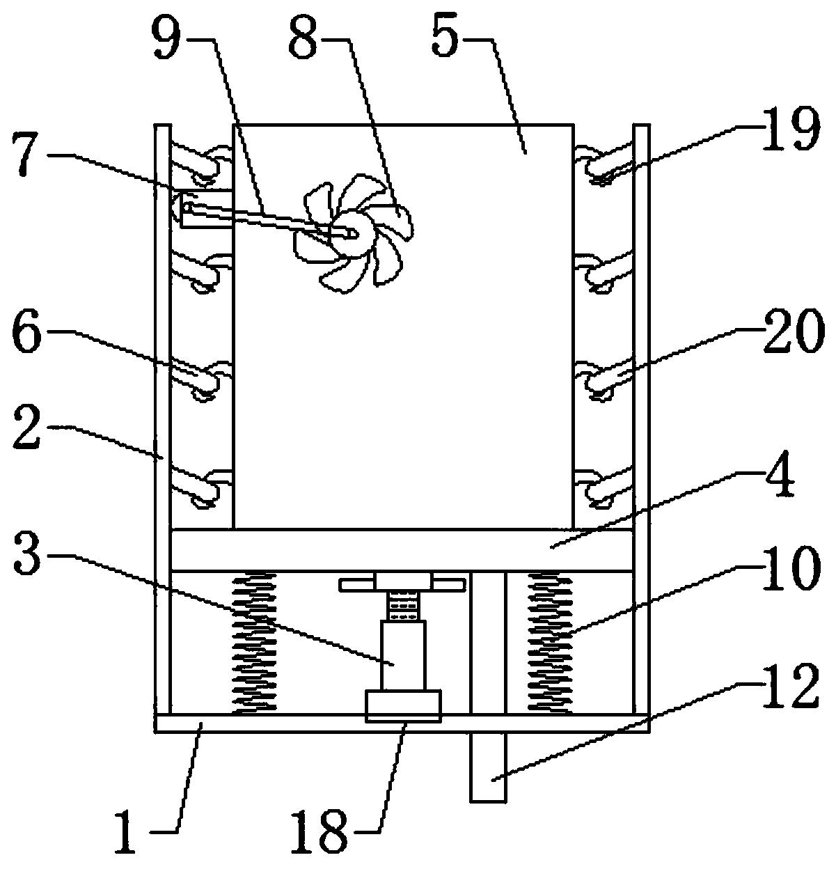
[0003] The invention provides an anti-shock power distribution cabinet, which solves the problem that the existing power distribution cabinet has a poor anti-seismic effect, and electric sparks and high temperatures are easily generated inside when violent vibrations occur in the event of natural disasters such as earthquakes, and the power distribution cabinet cannot be effectively avoided. There is a fire inside, and at the same time, when there is too much water outside, it cannot be effectively drained, and the internal wiring of the power distribution cabinet cannot be quickly sorted out.

Method used


Image

  • Shockproof power distribution cabinet
  • Shockproof power distribution cabinet
  • Shockproof power distribution cabinet

Examples


Embodiment Construction

[0026] In order to make the technical problems, technical solutions and advantages to be solved by the present invention clearer, the following will describe in detail with reference to the drawings and specific embodiments.

[0027] In the description of the present invention, it should be noted that the terms "center", "upper", "lower", "left", "right", "vertical", "horizontal", "inner", "outer", " The orientation or positional relationship indicated by "front", "rear", etc. is based on the orientation or positional relationship shown in the drawings, which is only for the convenience of describing the present invention and simplifying the description, rather than indicating or implying that the referred device or element must have a specific orientation, are constructed and operate in a particular orientation and therefore are not to be construed as limiting the invention. In addition, the terms "first", "second", and "third" are used for descriptive purposes only, and shou...


PUM

PropertyMeasurementUnit
The inside diameter ofaaaaaaaaaa

Abstract

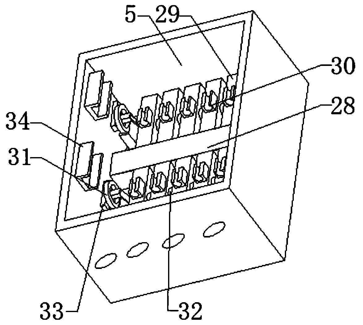
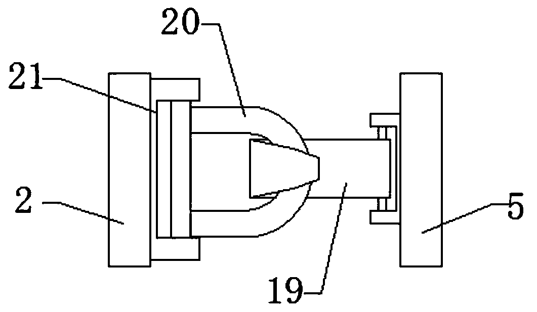
The invention discloses a shockproof power distribution cabinet. The shockproof power distribution cabinet comprises a bottom plate, side plates are fixedly connected to the two ends of the top of thebottom plate. The two ends of the top of the bottom plate are fixedly connected with power distribution cabinets through springs. Two sides of the power distribution cabinet are connected with the side plates through hook chain structures; a roller is installed on one side of the power distribution cabinet, the outer side of the roller makes contact with the side plates, fan blades are installedin the power distribution cabinet, a rotating shaft of the roller and rotating shafts of the fan blades are in transmission connection with each other through a belt, the two ends of the top of the bottom plate are fixedly connected with sliding plates through springs, and an installation area and a wire area are arranged on one side of the inner wall of the power distribution cabinet. The temperature in the power distribution cabinet can be reduced; the shockproof effect of the power distribution cabinet is enhanced, the problems that electric sparks and high temperature are easily generatedin the power distribution cabinet due to violent vibration when the power distribution cabinet encounters natural disasters such as earthquakes and the like, fire inside the power distribution cabinetcannot be avoided, and lines inside the power distribution cabinet cannot be quickly and clearly sorted when being disordered are effectively solved, and meanwhile water can be effectively drained when external accumulated water is excessive.

Description

technical field [0001] The invention relates to the technical field of electrical equipment, in particular to an anti-shock distribution cabinet. Background technique [0002] The power distribution cabinet (box) is divided into power distribution cabinet (box), lighting distribution cabinet (box), metering cabinet (box), and is the final equipment of the power distribution system. The cabinet is used in the occasions where the load is relatively scattered and there are few circuits; the motor control center is used in the occasions where the load is concentrated and there are many circuits. They distribute the electric energy of a certain circuit of the upper-level power distribution equipment to the nearby load. The load provides protection, monitoring and control. However, the existing power distribution cabinets have poor anti-seismic effect. When violent vibrations occur during earthquakes and other natural disasters, electric sparks and high temperatures are easily ge...

Claims


Application Information

Patent Timeline
IPC IPC(8): H02B1/30H02B1/54H02B1/56H02B1/28H02B1/20H02B1/24
CPCH02B1/202H02B1/24H02B1/28H02B1/30H02B1/303H02B1/306H02B1/54H02B1/565
Inventor 张勇
Owner SHENZHEN DONGSHENGYUAN ELECTRICAL EQUIP
Learn More