
A cooling device for power distribution cabinet based on centrifugal principle

A heat dissipation device and power distribution cabinet technology, which is applied in the substation/power distribution device shell, cooling/ventilation of substation/switchgear, substation/switch layout details, etc., can solve the problem of affecting the normal operation of electrical equipment in the power distribution cabinet Replacement costs, accelerated aging of electrical equipment, etc., to achieve the effect of increasing air flow, reducing dust entry, and increasing heat dissipation

Inactive Publication Date: 2020-12-11
FUJIAN DATANG INT NINGDE POWER GENERATION
View PDF9 Cites 0 Cited by
  • Summary
  • Abstract
  • Description
  • Claims
  • Application Information

AI Technical Summary

Problems solved by technology

[0003] During the use of the power distribution cabinet, the heat dissipation, dust insulation and waterproof effects of the power distribution cabinet are usually considered. However, the existing power distribution cabinets often pay attention to the heat dissipation effect of the power distribution cabinet and sacrifice the dustproof effect of the power distribution cabinet. There are louvers on the surface of the cabinet to achieve the effect of heat dissipation, but the heat dissipation effect of this method is poor, which will easily lead to accelerated aging of the electrical equipment inside the power distribution cabinet, increase the cost of parts replacement, poor heat dissipation, and even cause The electrical equipment is damaged due to high temperature, which causes circuit failure and unnecessary economic losses. Moreover, due to the direct opening of the shutters, the inside and outside of the power distribution cabinet are connected for a long time, which makes it easy for dust and moisture to pass through the shutters. Entering the inside of the power distribution cabinet, and dust entering the power distribution cabinet will accelerate the aging of the electrical equipment inside the power distribution cabinet. A large amount of dust will also affect the heat dissipation of the power distribution cabinet and affect the normal operation of the electrical equipment inside the power distribution cabinet. It is easy to directly induce damage to the electrical equipment inside the power distribution cabinet.

Method used


Image

  • A cooling device for power distribution cabinet based on centrifugal principle
  • A cooling device for power distribution cabinet based on centrifugal principle
  • A cooling device for power distribution cabinet based on centrifugal principle

Examples


Embodiment Construction

[0036] The following will clearly and completely describe the technical solutions in the embodiments of the present invention with reference to the accompanying drawings in the embodiments of the present invention. Obviously, the described embodiments are only some, not all, embodiments of the present invention. Based on the embodiments of the present invention, all other embodiments obtained by persons of ordinary skill in the art without making creative efforts belong to the protection scope of the present invention.

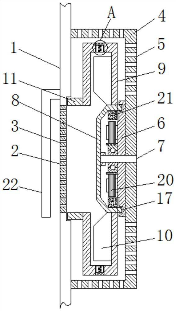
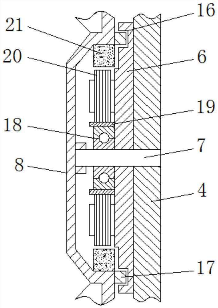
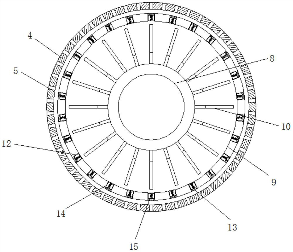
[0037] see Figure 1-8 , a cooling device for a power distribution cabinet based on the centrifugal principle, including a cabinet body 1, a dust shield 2, an air inlet hole 3, a fan cover 4, an air outlet hole 5, a motor base 6, a motor shaft 7, a cover plate 8, a rotor Plate 9, fan blade 10, first sealing ring 11, air outlet 12, sealing plate 13, sliding rod 14, spring 15, annular groove 16, second sealing ring 17, bearing 18, bearing seat 19, stator rotatin...


PUM


Abstract

The invention relates to the technical field of electrical engineering. The invention further discloses a power distribution cabinet heat dissipation device based on the centrifugal principle. The cabinet comprises a cabinet body, a dust baffle is fixedly connected to the interior of the cabinet body; an air inlet hole is formed in the dust baffle; a fan cover is fixedly connected to the interiorof the cabinet body; an air outlet hole is formed in the surface of the fan cover; a motor base is fixedly connected to the interior of the air outlet hole; a motor shaft is movably connected to the interior of the fan cover; a cover plate is fixedly connected to the outer part of the motor shaft; a rotating plate is fixedly connected to the outer part of the cover plate; fan blades are fixedly connected to the outer part of the rotating plate; through cooperative use of the rotating plate and the fan blades, the air flowing speed is increased, the air flowing speed in the power distribution cabinet is further increased, the heat dissipation effect is improved, normal operation of electrical elements in the power distribution cabinet is ensured, the service life of the electrical elementsin the power distribution cabinet is prolonged, and the maintenance cost of equipment is reduced.

Description

technical field [0001] The invention relates to the technical field of electrical engineering, in particular to a cooling device for a power distribution cabinet based on the centrifugal principle. Background technique [0002] The power distribution cabinet is the general name of the motor control center. The power distribution cabinet is used in the occasions where the load is relatively scattered and the circuit is less; they distribute the electric energy of a certain circuit of the upper-level power distribution equipment to the nearby load, and this level of equipment should provide loads. Protection, monitoring and control, with the development of electrical engineering, distribution cabinets are also increasingly developed. [0003] During the use of the power distribution cabinet, the heat dissipation, dust insulation and waterproof effects of the power distribution cabinet are usually considered. However, the existing power distribution cabinets often pay attention...

Claims


Application Information

Patent Timeline
Patent Type & Authority Patents(China)
IPC IPC(8): H02B1/56H02B1/30H02B1/28
CPCH02B1/28H02B1/30H02B1/565
Inventor 邱东升
Owner FUJIAN DATANG INT NINGDE POWER GENERATION
Learn More