
High-voltage direct-current power transmission trigger pulse control method and device

A technology of high-voltage direct current transmission and trigger pulse, which is applied in the output power conversion device, the conversion of alternating current power input to direct current power output, electrical components, etc. Stability and other issues, to achieve the effect of improving the degree of freedom and accuracy, improving the degree of control freedom, and improving the commutation ability

Active Publication Date: 2020-01-17
ELECTRIC POWER RESEARCH INSTITUTE, CHINA SOUTHERN POWER GRID CO LTD +1
View PDF5 Cites 1 Cited by
  • Summary
  • Abstract
  • Description
  • Claims
  • Application Information

AI Technical Summary

Problems solved by technology

However, when the AC voltage is unbalanced or the waveform is distorted, the pulse interval of each phase will be different, which will easily generate non-characteristic harmonics and cause harmonic instability. This method is no longer used in existing DC projects.
The second is equal interval pulse control. The PLL (Phase Locked Loop) circuit forms the phase control reference point, and then forms the trigger pulse through phase shifting. The trigger angle of each converter valve is uniformly controlled. However, under the equal interval pulse control, when the fault When the DC current rises, the voltage amplitude decreases, and the phase angle shifts during phase locking, the commutation angle that the HVDC transmission system can provide is smaller than the actual demand value, which may easily cause commutation failure and cause high-voltage DC transmission system failure. voltage instability

Method used


Image

  • High-voltage direct-current power transmission trigger pulse control method and device
  • High-voltage direct-current power transmission trigger pulse control method and device
  • High-voltage direct-current power transmission trigger pulse control method and device

Examples


Embodiment Construction

[0060] The following will clearly and completely describe the technical solutions in the embodiments of the present invention with reference to the accompanying drawings in the embodiments of the present invention. Obviously, the described embodiments are only some, not all, embodiments of the present invention. Based on the embodiments of the present invention, all other embodiments obtained by persons of ordinary skill in the art without making creative efforts belong to the protection scope of the present invention.

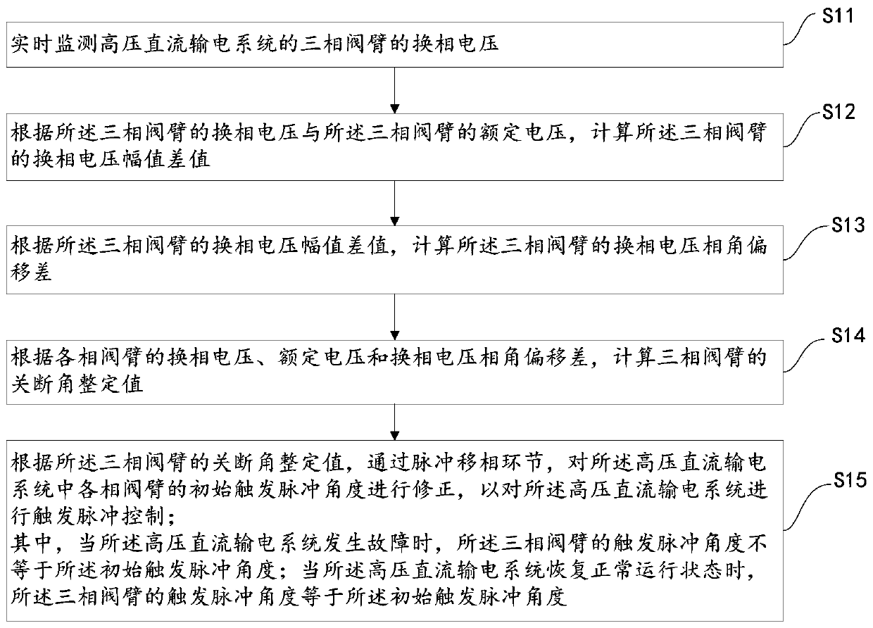
[0061] see figure 1 , which is a flow chart of a high-voltage direct current transmission trigger pulse control method provided by an embodiment of the present invention. The high-voltage direct current transmission trigger pulse control method includes the following steps:

[0062] S11: Real-time monitoring of the commutation voltage of the three-phase valve arm of the HVDC transmission system.

[0063] In the embodiment of the present invention, a voltage t...


PUM


Abstract

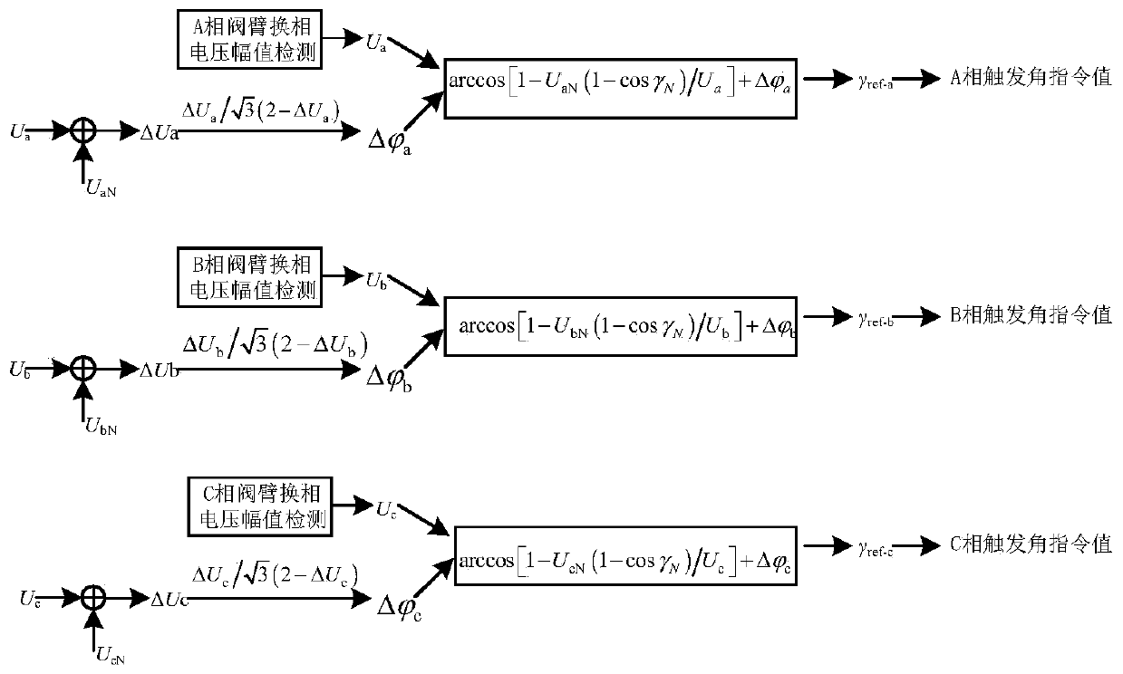
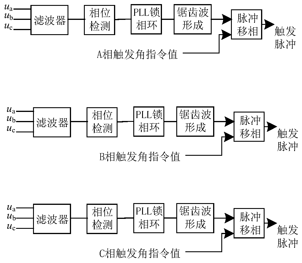
The invention discloses a high-voltage direct-current power transmission trigger pulse control method and device. The method comprises the following steps: monitoring commutation voltage of a three-phase valve arm of a high-voltage direct-current power transmission system in real time; calculating a commutation voltage amplitude difference value of the three-phase valve arm according to the commutation voltage of the three-phase valve arm and the rated voltage of the three-phase valve arm; calculating a commutation voltage phase angle deviation difference of the three-phase valve arm accordingto the commutation voltage amplitude difference of the three-phase valve arm; correcting the initial trigger pulse angle of each phase of valve arm in the high-voltage direct-current power transmission system according to the commutation voltage, the rated voltage and the commutation voltage phase angle deviation difference of each phase of valve arm to obtain a turn-off angle setting value of athree-phase valve arm; performing trigger pulse control on the high-voltage direct-current power transmission system according to the turn-off angle setting value of the three-phase valve arm. By using the method, the trigger pulse can be corrected in a targeted mode when the system breaks down, the control freedom degree of each phase valve set is improved, the phase changing capacity of the system is improved, and the voltage stability of the system is guaranteed.

Description

technical field [0001] The invention relates to the field of high voltage direct current transmission control, in particular to a high voltage direct current transmission trigger pulse control method and device. Background technique [0002] There are two main trigger pulse mechanisms for HVDC transmission systems: one is individual phase control, and the control circuit forms the required trigger pulses through phase shifting according to the moment when the voltage of each phase crosses zero. However, when the AC voltage is unbalanced or the waveform is distorted, the pulse interval of each phase will be different, which will easily generate non-characteristic harmonics and cause harmonic instability. This method is no longer used in existing DC projects. The second is equal interval pulse control. The PLL (Phase Locked Loop) circuit forms the phase control reference point, and then forms the trigger pulse through phase shifting. The trigger angle of each converter valve i...

Claims


Application Information

Patent Timeline
Patent Type & Authority Applications(China)
IPC IPC(8): H02J3/36H02M7/00H02M7/757
CPCH02J3/36H02M7/00H02M7/7575Y02E60/60
Inventor 李春华李明魏承志刘阳张祖安黄润鸿
Owner ELECTRIC POWER RESEARCH INSTITUTE, CHINA SOUTHERN POWER GRID CO LTD
Learn More