Highway and railway dual-purpose direct-hanging type container semi-trailer
A container and semi-trailer technology, applied to rail and road dual-purpose vehicles, vehicles used for freight, tractor-trailer combination, etc., can solve the problems of low transportation economy and decompression, and achieve improved economy and structure The effect of high strength and good bearing capacity
- Summary
- Abstract
- Description
- Claims
- Application Information
AI Technical Summary
Problems solved by technology
Method used
Image
Examples
Embodiment 1
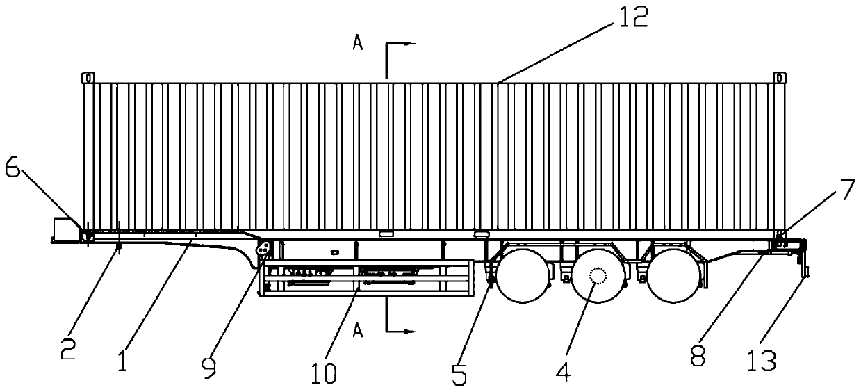
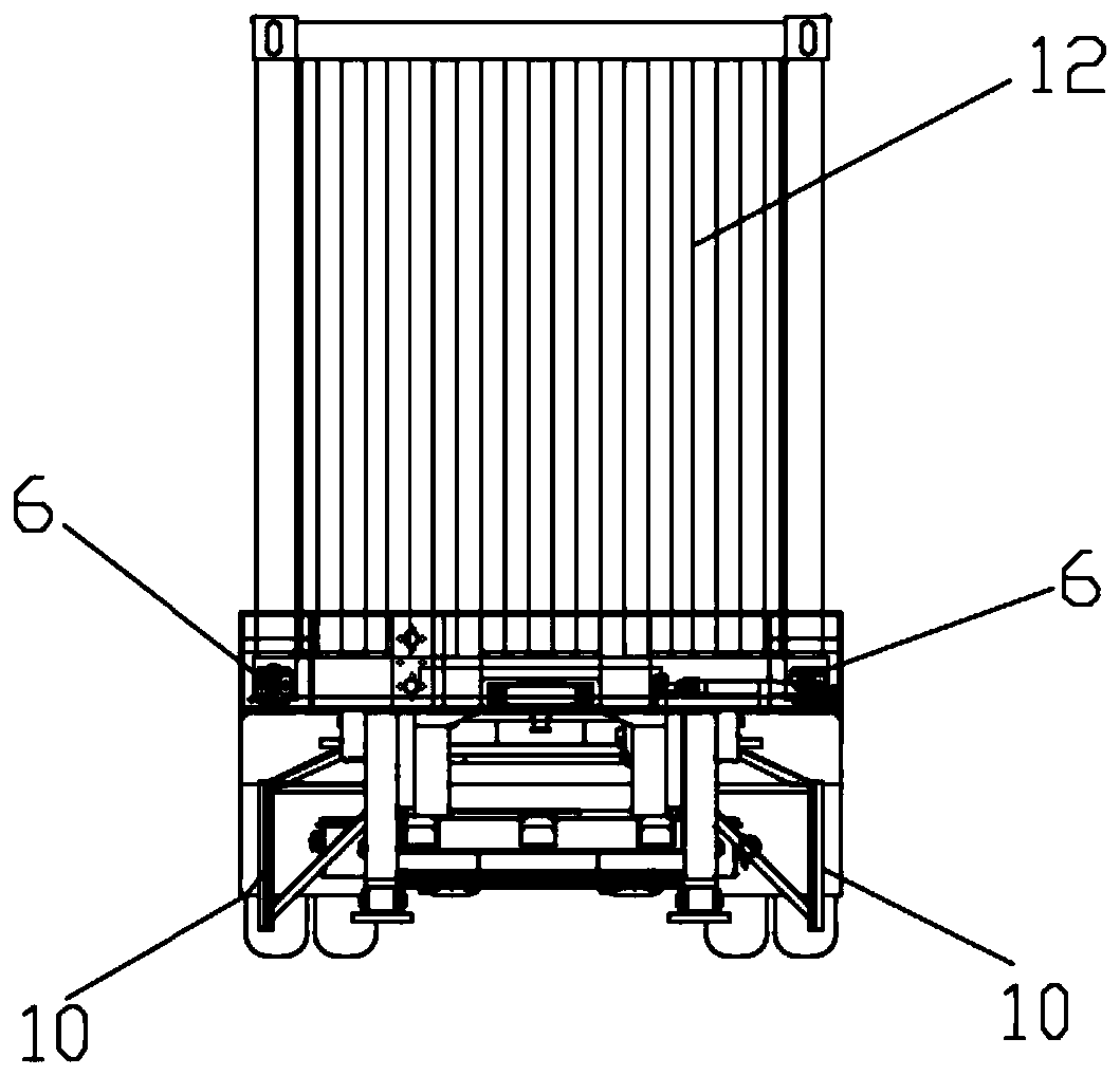
[0048] Embodiment one is basically as Figure 1 to Figure 3 As shown: this embodiment provides a dual-purpose direct-mounted container semi-trailer for roads and railways. The structure of the semi-trailer can be used as a load-bearing structure for container 12 railway transportation. When entering the railway transportation, the semi-trailer does not need to be hoisted by hoisting equipment Carry out transport on the railway special transport vehicle; The present embodiment container semi-trailer comprises vehicle frame 1, supporting device 9, side protection 10, air suspension 5, axle 4, railway operation air braking force and signal transmission device 8, rear protection 13 And road operation brake system 11 etc., wherein rear protection is the overturning structure, and it is turned down when the road is running, and it is turned up when the railway is running. Wheel axle 4, supporting device 9, side protection 10, railway operation air braking force and signal transmissi...
Embodiment 2
[0055] The second embodiment is basically the same as the first embodiment, the difference is that in order to conveniently and stably lock the front end of the container 12, this embodiment is provided with positioning bolt devices 6 on both sides of the front end beam 1.1 of the vehicle frame 1, two The left and right sides of the front end of the container 12 that the positioning bolt device 6 is correspondingly loaded into are relatively arranged, as Figure 8 to Figure 10 As shown, the positioning bolt device 6 specifically includes a positioning bolt 6.1 and a casing 6.2 sleeved on the outside of the positioning bolt 6.1. The casing 6.2 is fixedly installed on the bottom plate 1.1.1 of the front end beam 1.1, between the casing 6.2 and the positioning bolt 6.1. A steel spring 6.3 is provided, and the pre-compression force of the steel spring 6.3 always maintains the positioning bolt 6.1 on the side of the front end beam bottom plate 1.1.1 close to the bushing 6.2, and the...
Embodiment 3
[0059] The third embodiment is basically the same as the second embodiment, the difference is: please refer to Figure 11 to Figure 14 As shown, the passive lifting air suspension 5 provided in this embodiment includes a bracket 5.2 and a suspension airbag 5.3 fixed on the vehicle frame 1, and the bracket 5.2 and the suspension airbag 5.3 are respectively fixed on the vehicle on both sides of the wheel axle 4 of the vehicle body. On the frame 1, a guide arm 5.1 is also provided in this embodiment. The left end of the guide arm 5.1 is rotationally connected with the support 5.2 through a hinge 5.6. The hinge 5.6 in this embodiment is preferably a round pin, and the right end of the guide arm 5.1 is connected to the cantilever airbag through a bolt. The lower end is fixedly connected, and the wheel shaft 4 is fixed on the middle part of the guide arm 5.1 through a U-shaped bolt 5.7. The air spring in the prior art of the suspension air bag 5.3 provided in this implementation can ...
PUM
 Abstract
Description
Claims
Application Information
 - R&D
- Intellectual Property
- Life Sciences
- Materials
- Tech Scout
- Unparalleled Data Quality
- Higher Quality Content
- 60% Fewer Hallucinations
Browse by: Latest US Patents, China's latest patents, Technical Efficacy Thesaurus, Application Domain, Technology Topic, Popular Technical Reports.
© 2025 PatSnap. All rights reserved.Legal|Privacy policy|Modern Slavery Act Transparency Statement|Sitemap|About US| Contact US: help@patsnap.com


