Floating tip cone device for vertical spool take-up machine

A wire take-up machine and floating top technology, which is applied in transportation and packaging, delivery of filamentous materials, thin material processing, etc., can solve problems such as increased vibration of the fuselage, safety accidents, and parts that are easy to hurt operators, and achieve The effect of avoiding safety accidents

Pending Publication Date: 2020-01-21
GUIZHOU AEROSPACE NANHAI SCI & TECH
View PDF0 Cites 2 Cited by
  • Summary
  • Abstract
  • Description
  • Claims
  • Application Information

AI Technical Summary

Problems solved by technology

[0002] Wire drawing machine, wire drawing machine, vertical I-wheel take-up machine and other equipment constitute the steel wire drawing production line. The function of the vertical I-wheel take-up machine is to evenly rewind the finished steel wire drawn by the wire drawing machine according to certain requirements. To the I-shaped wheel; at present, the I-shaped wheel installed on the vertical I-shaped wheel take-up machine is located on the power turntable and positioned by the centering mandrel. The centering mandrel is about 50-100mm higher than the I-shaped wheel. In order to facilitate the loading of the empty I-shaped wheel and the lifting of the full I-shaped wheel, there is a gap of 0.3mm-0.5mm between the I-shaped wheel and the centering mandrel hole, and wear-resistant rubber is placed between the power turntable and the end face of the I-shaped wheel. The wheel and the power turntable are distributed and connected to realize the transmission of mutual rotational power; in order to increase the output value rate of a single machine and increase the output value under the depreciation unit of a single machine, it is necessary to increase the current take-up speed of the take-up machine, but due to the I-shaped wheel and the centering There is a gap in the installation of the mandrel hole. When the take-up speed is greater than 8m / s, the vibration of the fuselage caused by the relative movement between the I-shaped wheel and the centering mandrel will increase, which will easily cause the equipment parts to fall off and fly out. It is also easy to injure the operator and cause a safety accident.

Method used


Image

  • Floating tip cone device for vertical spool take-up machine
  • Floating tip cone device for vertical spool take-up machine
  • Floating tip cone device for vertical spool take-up machine

Examples


Embodiment Construction

[0030] The technical solution of the present invention is further described below, but the scope of protection is not limited to the description.

[0031] Such as Figure 1-6 shown.

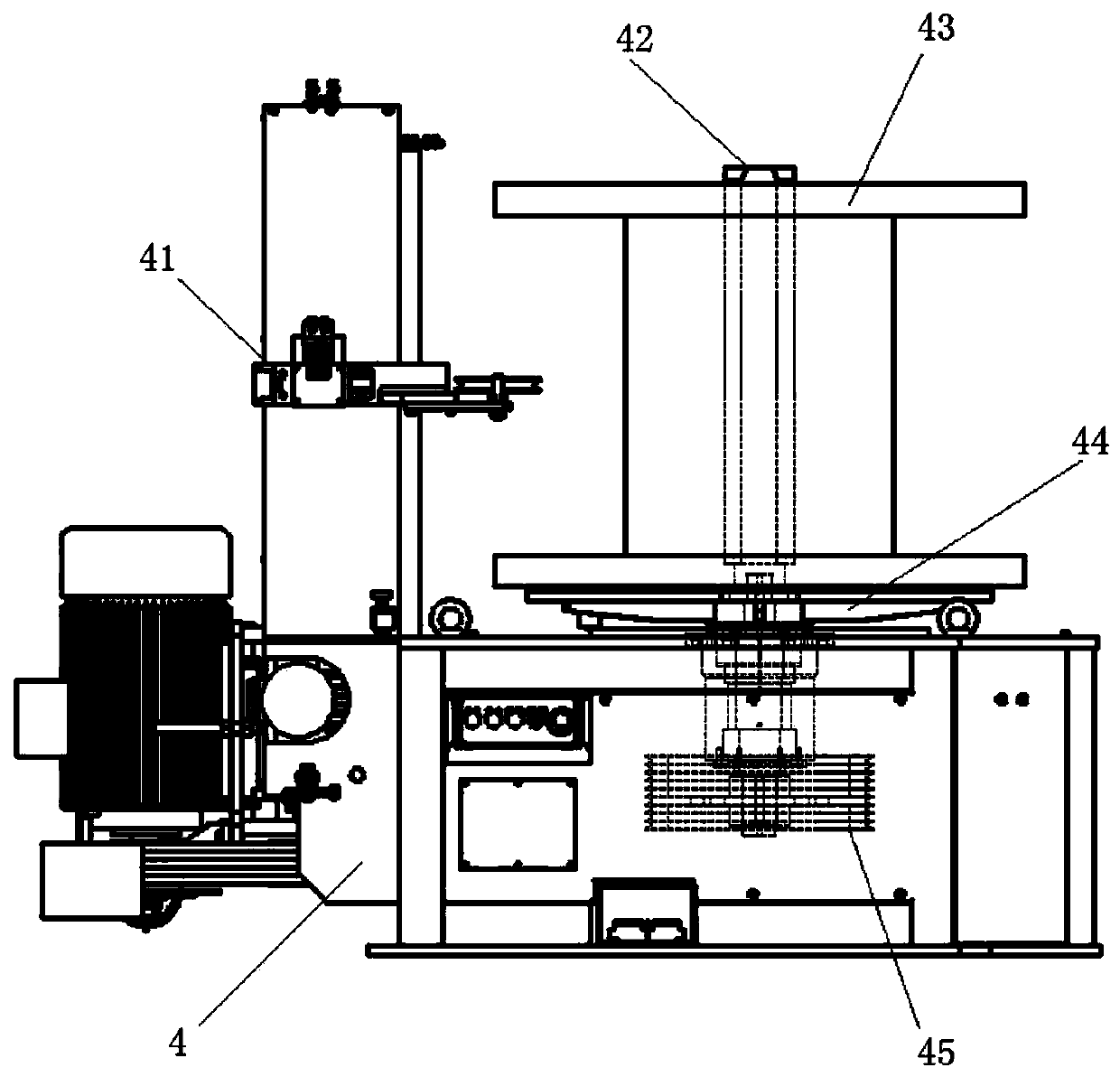
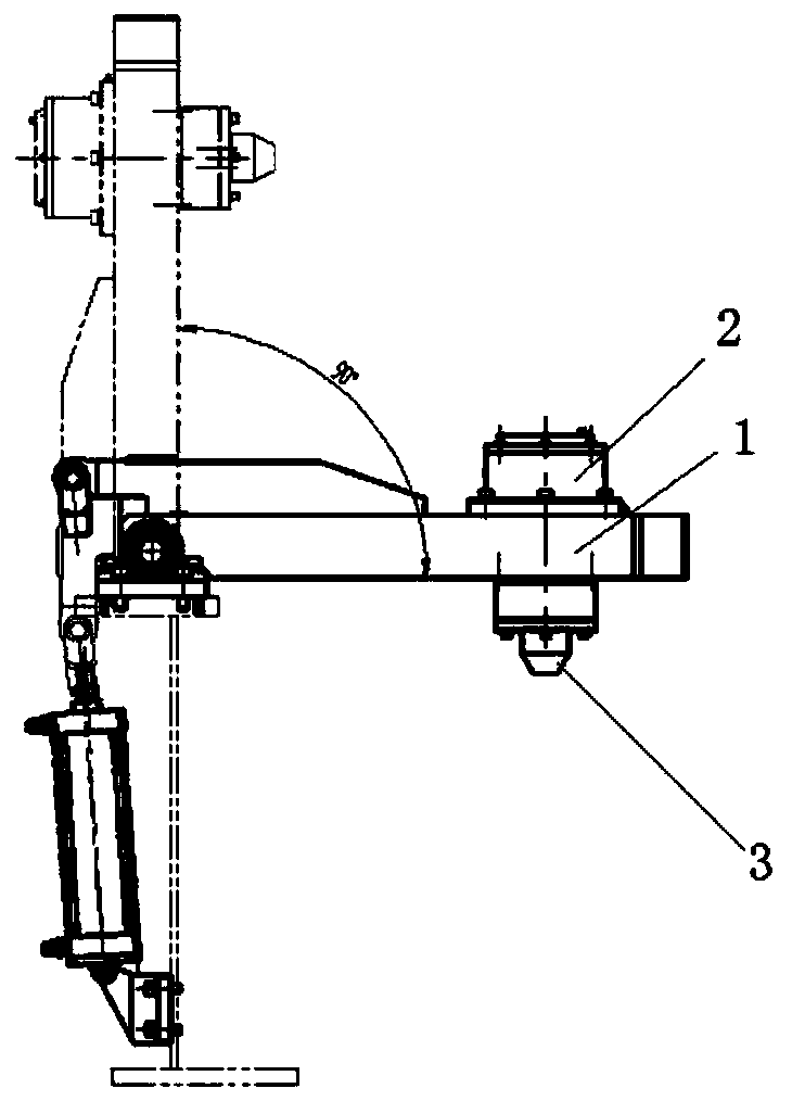
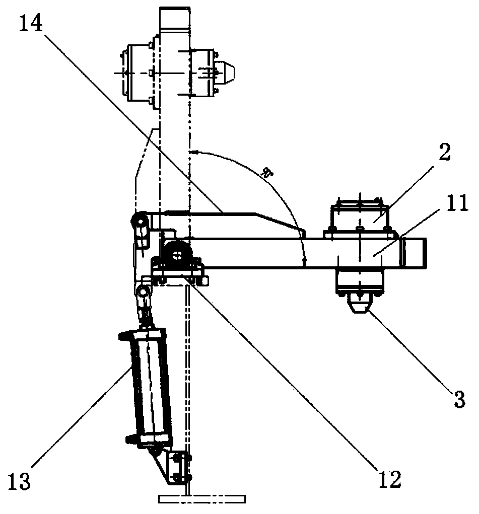
[0032] A floating top cone device for a vertical I-wheel take-up machine according to the present invention, which includes a bracket 1; a sleeve frame 2, which is fixedly installed on the sleeve frame 2 at the end of the bracket 1; a rotating shaft assembly 3, which is rotatably installed on the sleeve The rotating shaft assembly 3 inside the seat 2 , the rotating shaft assembly 3 includes a rotating shaft 31 .

[0033] The support 1 is fixedly mounted on the wire take-up machine 4, ensuring that the support 1 is perpendicular to the central axis of the centering mandrel 42, and the end of the rotating shaft 31 is in contact with the through hole on the centering mandrel 42 to ensure that the central axis of the rotating shaft 31 is in line with the fixed axis. The central axes of the central ...


PUM


Abstract

The invention discloses a floating tip cone device for a vertical spool take-up machine, and belongs to the technical field of steel wire drawing production equipment. The floating tip cone device comprises a support, a sleeve seat frame and a rotating shaft assembly, wherein the sleeve seat frame is fixedly mounted at the tail end of the support, the rotating shaft assembly is rotationally mounted in a sleeve seat, and the rotating shaft assembly comprises a rotating shaft. The support is fixedly mounted on the take-up machine, so that the support is perpendicular to the central axis of a centering mandrel, the tail end of the rotating shaft is in contact fit with a through hole in the centering mandrel, so that the central axis of the rotating shaft and the central axis of the centeringmandrel are collinear; and after a rotating belt wheel rotates to drive a power rotating disc, the centering mandrel is pressed by the rotating shaft, the spool take-up speed can be kept to be largerthan 8m / s, the problem that when the take-up speed is larger than 8m / s, the spool and the centering mandrel start to generate relative motion, and consequently machine body vibration is increased is solved, and the problems that equipment components fall off and fly out, and safety accidents are caused to operators due to the fact that the components fly out are avoided.

Description

technical field [0001] The invention belongs to the technical field of steel wire drawing production equipment, and relates to a floating top cone device for a vertical I-wheel take-up machine. Background technique [0002] Wire drawing machine, wire drawing machine, vertical I-wheel take-up machine and other equipment constitute the steel wire drawing production line. The function of the vertical I-wheel take-up machine is to evenly rewind the finished steel wire drawn by the wire drawing machine according to certain requirements. To the I-shaped wheel; at present, the I-shaped wheel installed on the vertical I-shaped wheel take-up machine is located on the power turntable and positioned by the centering mandrel. The centering mandrel is about 50-100mm higher than the I-shaped wheel. In order to facilitate the loading of the empty I-shaped wheel and the lifting of the full I-shaped wheel, there is a gap of 0.3mm-0.5mm between the I-shaped wheel and the centering mandrel hol...

Claims


Application Information

Patent Timeline
Patent Type & Authority Applications(China)
IPC IPC(8): B65H54/40B65H54/28
CPCB65H54/28B65H54/40
Inventor 孙明功吉明娟唐继超
Owner GUIZHOU AEROSPACE NANHAI SCI & TECH
Why Eureka
Try Eureka