Coal and biomass co-pyrolysis reaction device and method

A technology for a reaction device and biomass, which is applied to the co-pyrolysis device of coal and biomass, and the co-pyrolysis reaction field of coal and biomass, can solve the problems of low synergy effect and different pyrolysis intervals, so as to improve the product yield. And the effect of oil quality, simple and convenient process, oil yield and quality improvement

Active Publication Date: 2021-05-11
JIANGSU OCEAN UNIV
View PDF7 Cites 0 Cited by
  • Summary
  • Abstract
  • Description
  • Claims
  • Application Information

AI Technical Summary

Problems solved by technology

Essentially, the synergistic effect in the co-pyrolysis process of coal and biomass is that the free radical fragments produced by coal pyrolysis can be stabilized by small free radicals or hydrogen produced by biomass pyrolysis, while coal and biomass are different in structure, The pyrolysis range is also different. The main pyrolysis temperature range of biomass is 200-350°C, while the pyrolysis range of coal is mainly 400-600°C. During the pyrolysis process, the two are pyrolyzed successively, and the synergistic effect is not high, and some researchers even believe that there is no synergistic effect in the co-pyrolysis process.

Method used


Image

  • Coal and biomass co-pyrolysis reaction device and method
  • Coal and biomass co-pyrolysis reaction device and method
  • Coal and biomass co-pyrolysis reaction device and method

Examples


Embodiment 2

[0038] Embodiment 2, a method for coal and biomass co-pyrolysis reaction, using the coal and biomass co-pyrolysis reaction device described in Example 1, the steps are as follows:

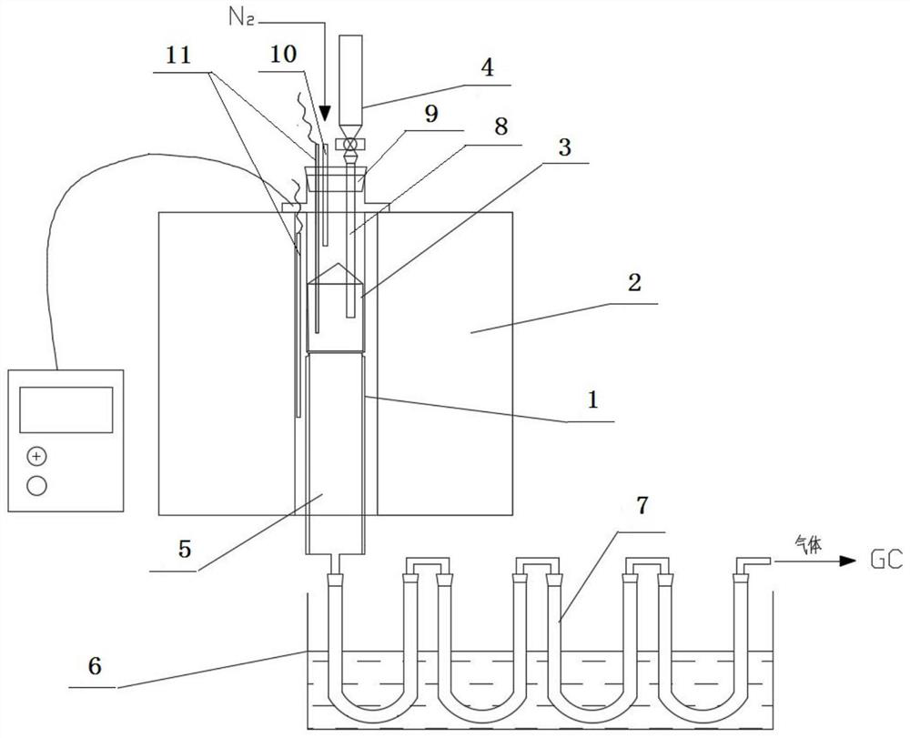
[0039] (1) Weigh a certain amount of coal and put it into the sample basket 3, put the biomass in the biomass feeder 4 and seal it, and connect the experimental device;

[0040](2) Feed nitrogen gas from the air inlet of rubber plug 9; open tubular heating furnace 2 to set the temperature rise program for heating; monitor the temperature of the co-pyrolysis reaction coal sample in real time through thermocouple thermometer 11; set the temperature rise rate of tubular heating furnace Set at 1-60°C / min;

[0041] (3) When the coal sample reaches the set temperature of 300-600°C, open the feeding valve, and the biomass falls into the sample basket 3 through the feeding pipe 8, and co-pyrolyzes with the coal being pyrolyzed; the co-pyrolysis reaction The final temperature is set at 600-800°C;

[0042]...

Embodiment 3

[0043] Example 3, a comparative experiment of coal and biomass co-pyrolysis reaction:

experiment example

[0044] Experimental example: refer to figure 1 , using the coal and biomass co-pyrolysis reaction device described in embodiment 1, wherein:

[0045] The tube heating furnace is an ordinary programmable tube heating furnace with an inner diameter of 20 mm and a length of 300 mm.

[0046] The inner diameter of the reaction pipe body 3 is 13.75mm, the wall thickness is 1mm, and the length is 400mm. The inner diameter of the sample basket 13 is 12mm, the wall thickness is 0.75mm, and the length is 100mm. The bottom of the sample basket 13 is perforated, and the copper mesh plate at the bottom can prevent coal dust and biomass Fall, guaranteed experimental results.

[0047] The condensing device is composed of 4 U-shaped tubes in series. The U-shaped tubes are placed in an ice-water bath, and the purpose of multi-stage condensation is to fully condense the tar in the pyrolysis gas to ensure the calculation of the yield and the determination of the gas phase composition.

[0048]...


PUM


Abstract

A coal and biomass co-pyrolysis reaction device and method, the device includes a tubular heating furnace, a reactor, a biomass feeder, a tar collection pipe and a cooling device; the reactor is fixedly installed in the tubular heating furnace, There is a movable sample basket in the middle of the reaction tube, and the sample basket is placed in the middle of the tubular heating furnace; the biomass feeder is located above the reactor, and the biomass feeder includes a hopper, and the lower part of the hopper is connected with a sample basket The feeding pipe in the middle is equipped with a feeding valve; a tar collecting pipe and a cooling device are used to cool and collect tar. The invention also discloses a co-pyrolysis reaction method for coal and biomass. Using the device for co-pyrolysis of coal and biomass in the present invention, the coal sample is first heated to a certain temperature at a certain heating rate, and then the biomass is added through a feeder. This can help to realize the "synchronous" pyrolysis of co-pyrolysis raw materials, which is beneficial to the synergistic effect of co-pyrolysis. Experiments have proved that the co-pyrolysis method not only requires small equipment volume and is easy to operate, but also can improve the co-pyrolysis oil yield and oil quality.

Description

technical field [0001] The invention relates to the technical fields of chemical industry and energy, in particular to a coal and biomass co-pyrolysis device; the invention also relates to a coal and biomass co-pyrolysis reaction method. Background technique [0002] Due to the decreasing reserves of petroleum resources and the oil crises that have emerged in recent years, pyrolysis technology for the purpose of producing liquid fuels has been extensively studied. Compared with individual pyrolysis of coal and biomass, coal and biomass co-pyrolysis technology is beneficial to environmental protection and sustainable development of energy resources on the one hand, and on the other hand, most researchers believe that biomass is a hydrogen-rich substance that can be used in co-pyrolysis In the process, it is used as a hydrogen supply agent for coal, thereby improving the oil and gas yield and oil and gas quality. Therefore, many researchers at home and abroad have conducted a...

Claims


Application Information

Patent Timeline
Patent Type & Authority Patents(China)
IPC IPC(8): C10G1/00
CPCC10G1/00C10G2300/1011
Inventor 何文静赵一博张兰君李航朱亚晴许抒悦
Owner JIANGSU OCEAN UNIV
Why Eureka
Try Eureka