An underwater dedusting and grinding machine

A technology of a leather machine and a rotating motor, which is applied in the field of underwater dust removal and leather grinding machine, can solve the problems of adhesion of dander, difficult to remove, and poor cleaning effect of abrasive debris, etc. Effect

Active Publication Date: 2021-05-28
平邑县经发企业服务有限公司
View PDF7 Cites 0 Cited by
  • Summary
  • Abstract
  • Description
  • Claims
  • Application Information

AI Technical Summary

Problems solved by technology

However, during the use of the equipment, when the dry brush rubs against the leather, static electricity will be generated, which will make the dander stick to the skin and be difficult to remove. At the same time, the dander is easy to accumulate in the bristles. getting worse gradually

Method used


Image

  • An underwater dedusting and grinding machine
  • An underwater dedusting and grinding machine
  • An underwater dedusting and grinding machine

Examples


Embodiment 1

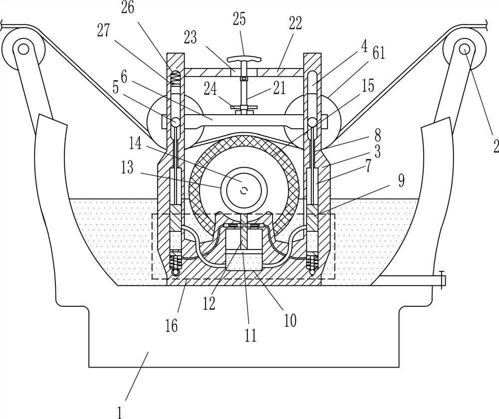
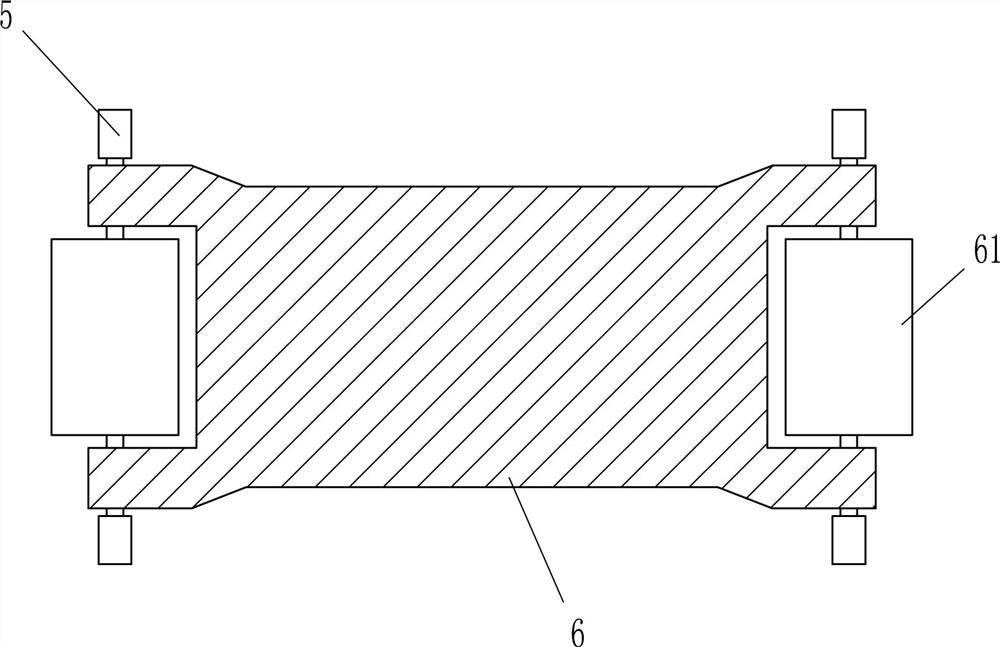
[0017] like Figure 1-3 As shown, an underwater dust-removing and leather grinding machine includes a liquid storage table 1, a guide roller 2, a mounting frame 3, a sliding shaft 5, a mounting plate 6, a pressing roller 61, a first cylinder 7, a connecting rod 8, a first A piston 9, a communication pipe 91, a second cylinder 10, a second piston 11, a bracket 12, a mounting seat 13, a rotating motor 14, a leather grinding wheel 15 and a clamping device 16, the liquid storage table 1 is symmetrically provided with left and right The guide roller 2 and the liquid storage table 1 are symmetrically provided with mounting brackets 3 in the front and rear through bolt connection. The mounting brackets 3 are all provided with sliding grooves 4, and sliding shafts 5 are movably arranged in the sliding grooves 4, and between the sliding shafts 5 A mounting plate 6 is provided, a pressure roller 61 is arranged symmetrically on the mounting plate 6, a first cylinder 7 is arranged symmetr...

Embodiment 2

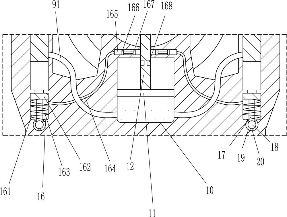
[0021] like figure 1 and image 3 As shown, on the basis of Embodiment 1, it also includes a moving rod 17, a clamping ball 18, an elastic ball groove 19 and a button 20, the bottom of the third piston 162 is provided with a moving rod 17 by means of screw connection, and the bottom of the moving rod 17 is provided with a moving rod 17. The clamping ball 18 is welded, the bottom of the third cylinder 161 is provided with an elastic ball groove 19, the clamping ball 18 is matched with the elastic ball groove 19, and the lower part of the elastic ball groove 19 is provided with a button 20, and the button 20 is connected to the rotating motor 14 through a line.

[0022] When the third piston 162 moves downward, the first elastic member 163 is compressed, the third piston 162 drives the moving rod 17 to drive the clamping ball 18 to move downward, and the clamping ball 18 is clamped into the elastic ball groove 19 to play a fixing role , the clamping ball 18 squeezes the button ...


PUM


Abstract

The invention belongs to the technical field of leather processing, and in particular relates to an underwater dust-removing leather grinding machine. The technical problem to be solved is how to provide an underwater dust-removing leather grinding machine that can avoid dander from adhering to leather. An underwater dust removal and leather grinding machine, including a liquid storage platform, a guide roller, a mounting frame, a sliding shaft, a mounting plate, a pressure roller, a first cylinder, a connecting rod, a first piston, a connecting pipe, a second cylinder, The second piston, etc.; guide rollers are arranged symmetrically on the left and right sides of the liquid storage platform, and mounting brackets are arranged symmetrically on the front and back of the liquid storage platform, and there are chutes on the mounting brackets, and sliding shafts are movable in the chute. A mounting plate is arranged between them, and pressure rollers are arranged symmetrically on the mounting plate. The invention achieves the effects of being able to avoid dander from adhering to the leather and from accumulating wear debris in the bristles.

Description

technical field [0001] The invention belongs to the technical field of leather processing, and in particular relates to an underwater dust-removing and leather-grinding machine. Background technique [0002] Leather is generally denatured and non-perishable animal skins obtained through physical and chemical processing such as depilation and tanning. It is used to wrap the surface of furniture such as sofas and seats, or to make relatively advanced materials such as mattresses and cushions. However, the existing leather functions are relatively simple, and they are only used to apply their own characteristics, and there is no in-depth excavation and development. With the rapid development of the social economy and the continuous improvement of people's living standards, the existing leather is far from meeting people's needs, but the leather grinding machine will generate a lot of dust during the working process, which not only pollutes the environment, but also affects the...

Claims


Application Information

Patent Timeline
Patent Type & Authority Patents(China)
IPC IPC(8): C14B1/44C14B17/14
CPCC14B1/44C14B17/14
Inventor 何晓琴古俊朋
Owner 平邑县经发企业服务有限公司
Why Eureka
Try Eureka