Height measurement level gage for building surveying and mapping
A technology of height measurement and leveling instrument, which is applied in the field of architectural surveying and mapping, can solve problems such as leveling shaft clearance shaking, vulnerability to weather conditions, unstable line of sight, etc., and achieve the effect of avoiding contact wear and excessive measurement error
- Summary
- Abstract
- Description
- Claims
- Application Information
AI Technical Summary
Problems solved by technology
Method used
Image
Examples
Embodiment 1
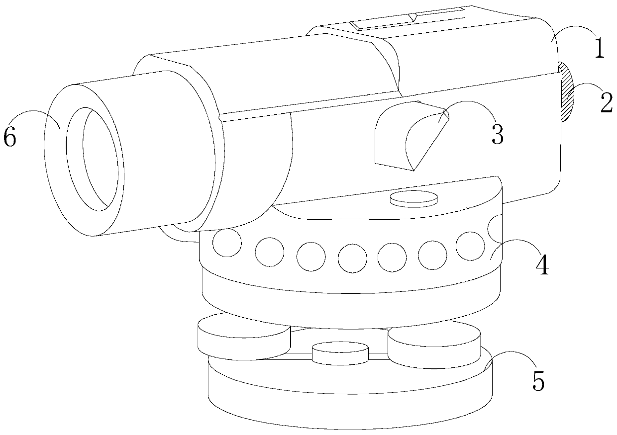
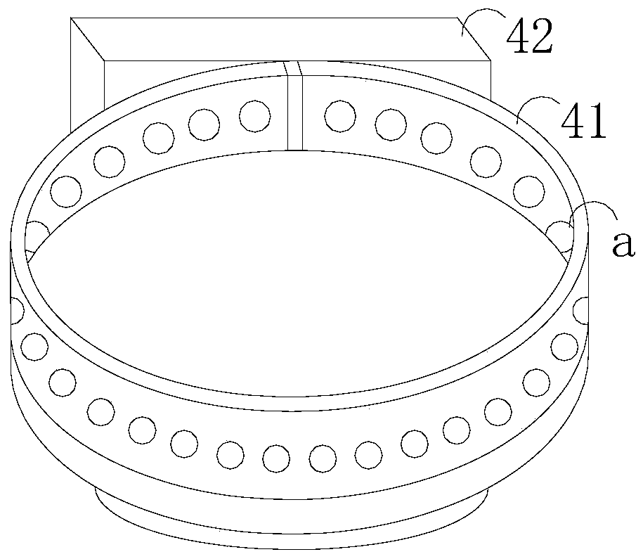
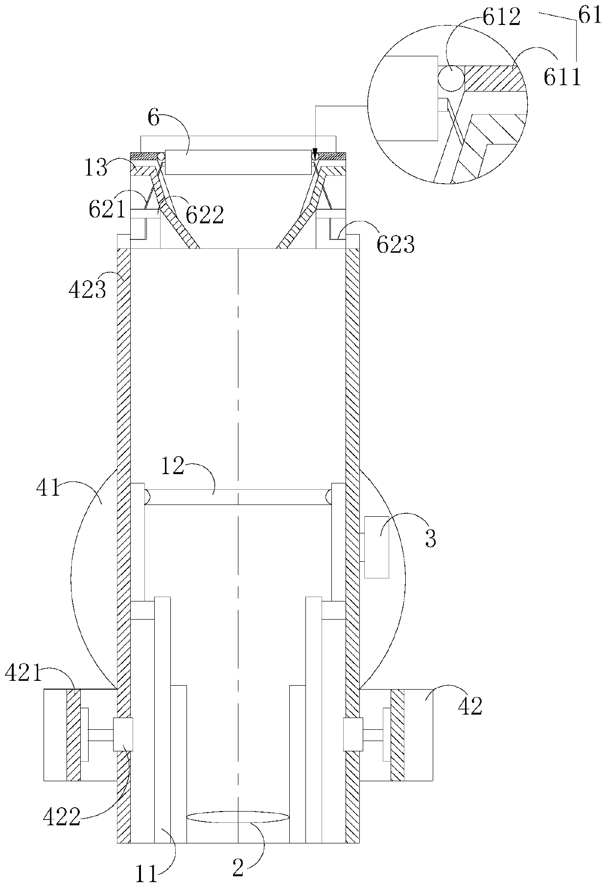
[0029] Such as Figure 1-Figure 3 As shown, the present invention provides a kind of height measuring level for building surveying and mapping, and its structure comprises frame 1, eyepiece 2, focusing screw 3, turntable 4, base 5, objective lens 6, and described frame 1 is provided with Control the focusing screw 3 of the eyepiece 2, the turntable 4 is installed on the base 5, the turntable 4 is fixed with a frame 1, and the frame 1 is provided with the eyepiece 2, the objective lens 6, and the focusing screw 3. The outer surface of the turntable 4 is provided with an outer retainer 41 and a connecting base 42, and more than two air holes a are evenly opened on the circumferential surface of the outer retaining ring 41, and a rotating handle is arranged inside the connecting base 42 421. Connect the rotating shaft 422 and the screw rod 423. The connecting rotating shaft 422 is equipped with a detection mechanism. The detection mechanism includes an air hole a, a probe b, a mo...
Embodiment 2
[0031] Such as Figure 5 As shown, more than two air holes a are uniformly opened on the circumferential surface of the outer retainer 41, and the inside of the air hole a has a filter mesh interlayer, the air hole a has double openings, and the inner opening matches the probe The gas sensing end of b can power off the dust particles in the wind through the filter in the interlayer, avoiding the accumulation of dust inside the probe b and the connection efficiency of the signal contact. The upper port of the probe b is open, and the upper opening Collect the gas from the wind hole a, push the built-in signal contact to start the motor c when the gas is increasing, and evenly distribute it on the turntable 4 through the circumference of the wind hole a to expand the wind detection range, The turntable 4 with concentrated wind force concentrates the gas on the air inlet of the probe b through the inner ring, so as to realize a more rapid and effective timely sensing of the wind ...
Embodiment 3
[0033] Such as Figure 4 and Figure 6 As shown, the pusher 61 includes a folding piece 611 and a pulley 612, the folding piece 611 is a horizontal spring type, the pulley 612 is provided with two, and is horizontally opposite, and there are two contact ends of the two pulleys 612. V-shaped incision, the traction structure 62 is composed of a traction bar 621, a push block 622, and a right-angle pull bar 623. The gap left by the horizontal end of the right-angle pull rod 623 is equal to the exposed width of the objective lens 6, and one end of the traction bar 621 passes through the objective lens supporting platform 13 and is fixed on both sides of the outer surface of the objective lens 6. The telescopic length of the right-angle pull rod 622 is the same as that of the objective lens 6. The activity gap is consistent to ensure that the surveying and mapping operation is closed within the effective inward movement range. During the closing process, the pulley 612 contacts th...
PUM
 Abstract
Description
Claims
Application Information
 - R&D
- Intellectual Property
- Life Sciences
- Materials
- Tech Scout
- Unparalleled Data Quality
- Higher Quality Content
- 60% Fewer Hallucinations
Browse by: Latest US Patents, China's latest patents, Technical Efficacy Thesaurus, Application Domain, Technology Topic, Popular Technical Reports.
© 2025 PatSnap. All rights reserved.Legal|Privacy policy|Modern Slavery Act Transparency Statement|Sitemap|About US| Contact US: help@patsnap.com


