
Inner liner underwater bubbling detection device and method

A detection device and liner technology, applied in the neural learning method, by detecting the appearance of fluid at the leakage point, using liquid/vacuum degree for liquid tightness measurement, etc., can solve the problem of high labor cost, high noise, and unreliable results to avoid on-site operations, reduce labor costs, and reduce interference

Pending Publication Date: 2020-01-21
合肥中科迪宏自动化有限公司
View PDF7 Cites 1 Cited by
  • Summary
  • Abstract
  • Description
  • Claims
  • Application Information

AI Technical Summary

Problems solved by technology

Production line workers conduct inspections through monotonous and repetitive labor. Such inspection results are unreliable and the labor cost is high. The staff need to work for a long time at the industrial site. Because the liner needs to be inflated and deflated at the site, the noise is huge, and it takes a long time to This environment seriously affects the health of the staff
In addition, manual observation of the bubbling of the water surface can only determine whether the inner tank is leaking. In many cases, the leaking part cannot be directly observed, which is not conducive to subsequent repair welding of the leaking part.

Method used


Image

  • Inner liner underwater bubbling detection device and method
  • Inner liner underwater bubbling detection device and method
  • Inner liner underwater bubbling detection device and method

Examples


Embodiment 1

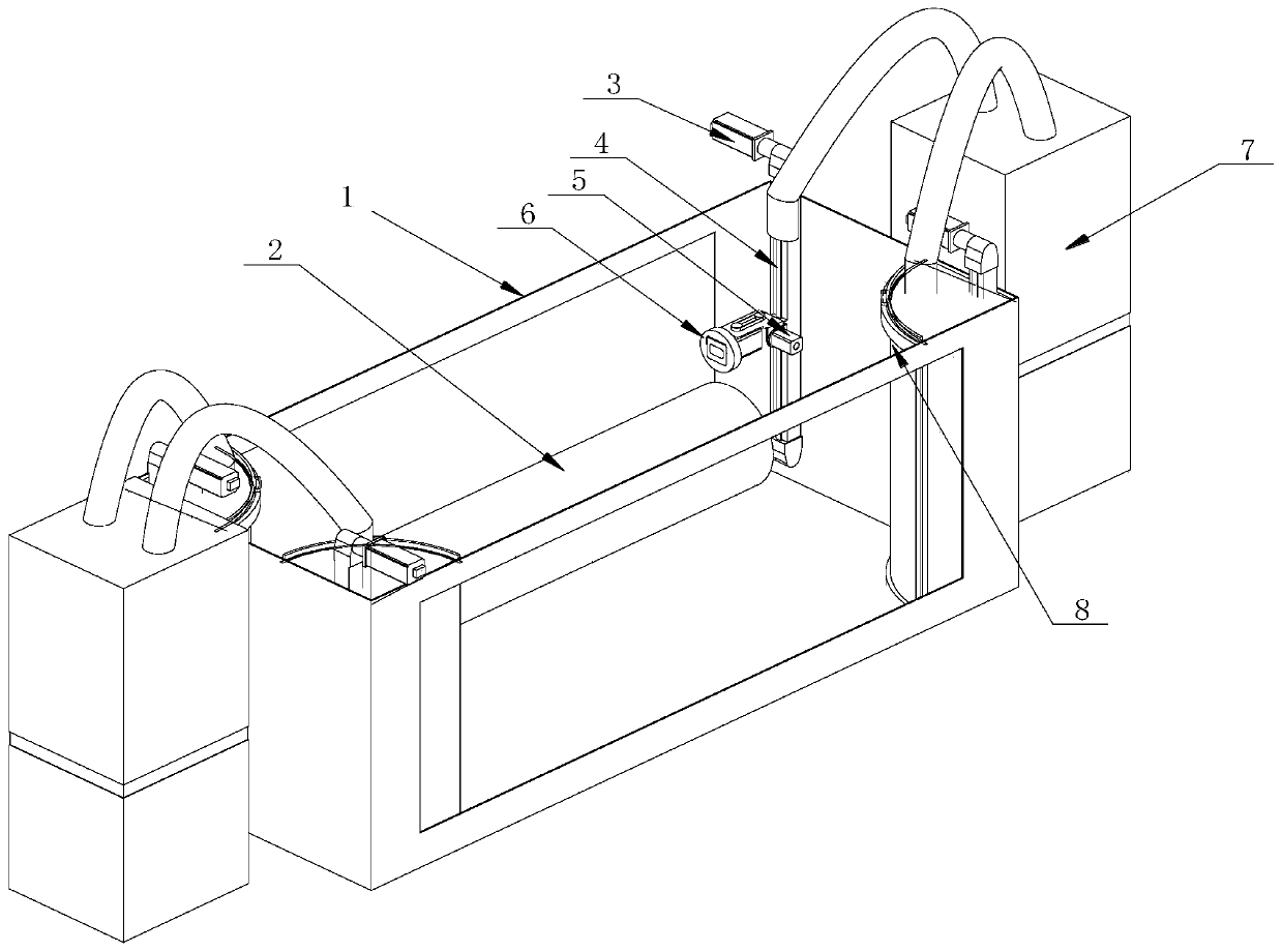
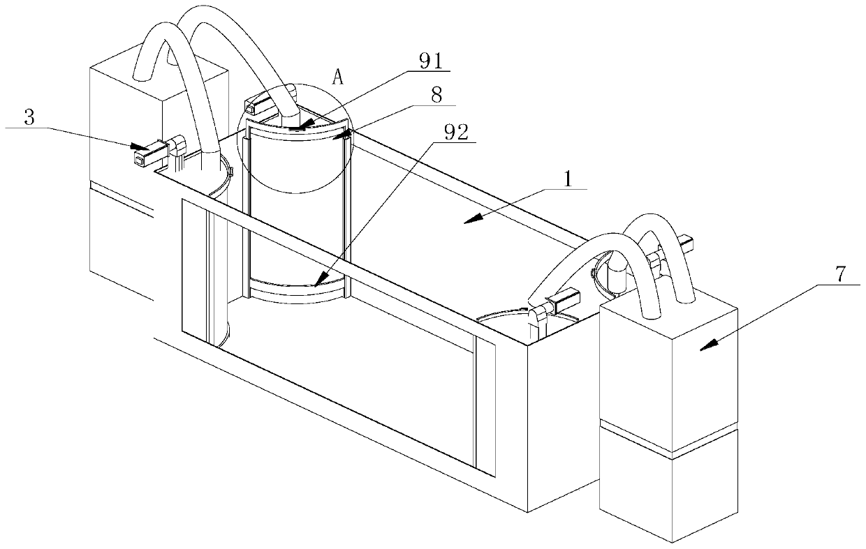
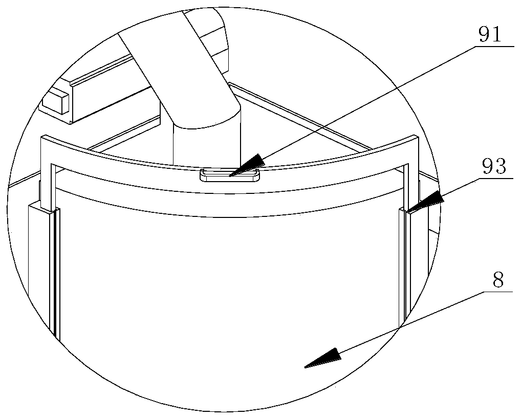
[0033] Such as Figure 1-3 As shown, the underwater bubbling detection device for the inner tank includes an isolation cavity 8 provided on the cylinder body 1 for immersing the inner tank 2, and the isolation cavity 8 is transparent and isolated from the liquid inside the cylinder body 1. A camera 6 is arranged in the isolation cavity 8, and the camera 6 is connected to an external signal processing module, and the signal processing module is connected to a host computer with a display. Optimally, the cylinder body 1 is also transparent.

[0034] A guide rail 4 is arranged in the isolation cavity 8 , and the camera 6 moves up and down in the isolation cavity 8 .

[0035] There are multiple isolation chambers 8, several of which are vertically arranged at the corners of the cylinder block 1, the guide rail 4 is vertically arranged in the isolation chamber 8, and the guide rail 4 is provided with a camera 6 sliding on the guide rail 4. The slider also includes a first driver ...

Embodiment 2

[0041] Using the method of the above-mentioned liner underwater bubbling detection device, the signal processing module includes a host computer, including the following steps:

[0042] The initial position of the camera 6 needs to be adjusted according to different liners 2 .

[0043] S1. When the liquid in the cylinder body 1 is not disturbed, turn on the camera 6 and the signal processing module, adjust the position of the camera 6, and obtain an image; after placing the liner 2 in the cylinder body 1, let it stand for the first set time; The first set time is 5 minutes.

[0044] S2. Move the camera 6 to a set position to acquire an image; take out the liner 2 from the cylinder body 1 . Before detecting the bubbles, first check the condition of the liner 2 entering and exiting the pool, and wait accordingly to avoid the interference of the suspended matter in the water at the industrial site (similar to the shape and size of the bubbles) to the bubble detection.


PUM


Abstract

The invention relates to the technical field of inner liner detection, in particular to an inner liner underwater bubbling detection device and method. The device comprises an isolation cavity, wherein the isolation cavity is formed on a cylinder body used for immersing an inner liner; the isolation cavity is transparent and is isolated from liquid inside the cylinder body; a camera is arranged inthe isolation cavity; and the camera is connected with an external signal processing module. The inner liner underwater bubbling detection device and method have the advantages that the camera arranged in the isolation cavity is used for observing the inner liner put in the cylinder body, so that field operation of personnel is avoided; in addition, the external signal processing module obtains images of the camera and then performs automatic detection on bubbles; and the device provides hardware support for realizing automatic bubble detection.

Description

technical field [0001] The invention relates to the technical field of liner detection, in particular to an underwater bubbling detection device and method for a liner. Background technique [0002] Whether the inner tank of the water heater leaks is one of the important standards for whether the water heater is qualified. At present, the method adopted in the industry is to inflate the inner tank and put it in the pool, and the workers observe the air bubbles on the water surface to detect the air leakage. Production line workers conduct inspections through monotonous and repetitive labor. The results of such inspections are unreliable and the labor costs are high. The staff need to work for a long time at the industrial site. Because the liner needs to be inflated and deflated on site, the noise is huge, and it takes a long time to This environment seriously affects the health of the staff. In addition, manual observation of the bubbling of the water surface can only dete...

Claims


Application Information

Patent Timeline
Patent Type & Authority Applications(China)
IPC IPC(8): G01M3/10G06T7/20G06N3/08
CPCG01M3/10G06N3/08G06T7/20
Inventor 孙丙宇周璠
Owner 合肥中科迪宏自动化有限公司
Learn More