
Large-target-surface miniaturized non-refrigeration infrared continuous zooming optical system

An uncooled infrared and optical system technology, applied in the field of large target miniaturized uncooled infrared continuous zoom optical system, can solve the problem of no continuous zoom optical system, avoid system complexity, reduce volume, and reduce system weight Effect

Active Publication Date: 2020-01-21
凯迈(洛阳)测控有限公司
View PDF8 Cites 0 Cited by
  • Summary
  • Abstract
  • Description
  • Claims
  • Application Information

AI Technical Summary

Problems solved by technology

[0003] At present, with the continuous progress of uncooled infrared technology, uncooled infrared detectors are also developing rapidly in the direction of high performance and low cost. They are mainly used to meet the requirements of high sensitivity, high resolution, high frame frequency and The need to replace some cooled detectors; domestic uncooled infrared detectors have been mass-produced as 1024×768 long-wave uncooled infrared detectors with a pixel size of 14 μm, but currently there is no long-wave uncooled infrared detector that can adapt to 1024×768 long-wave uncooled detectors Continuous zoom optics for the detector

Method used

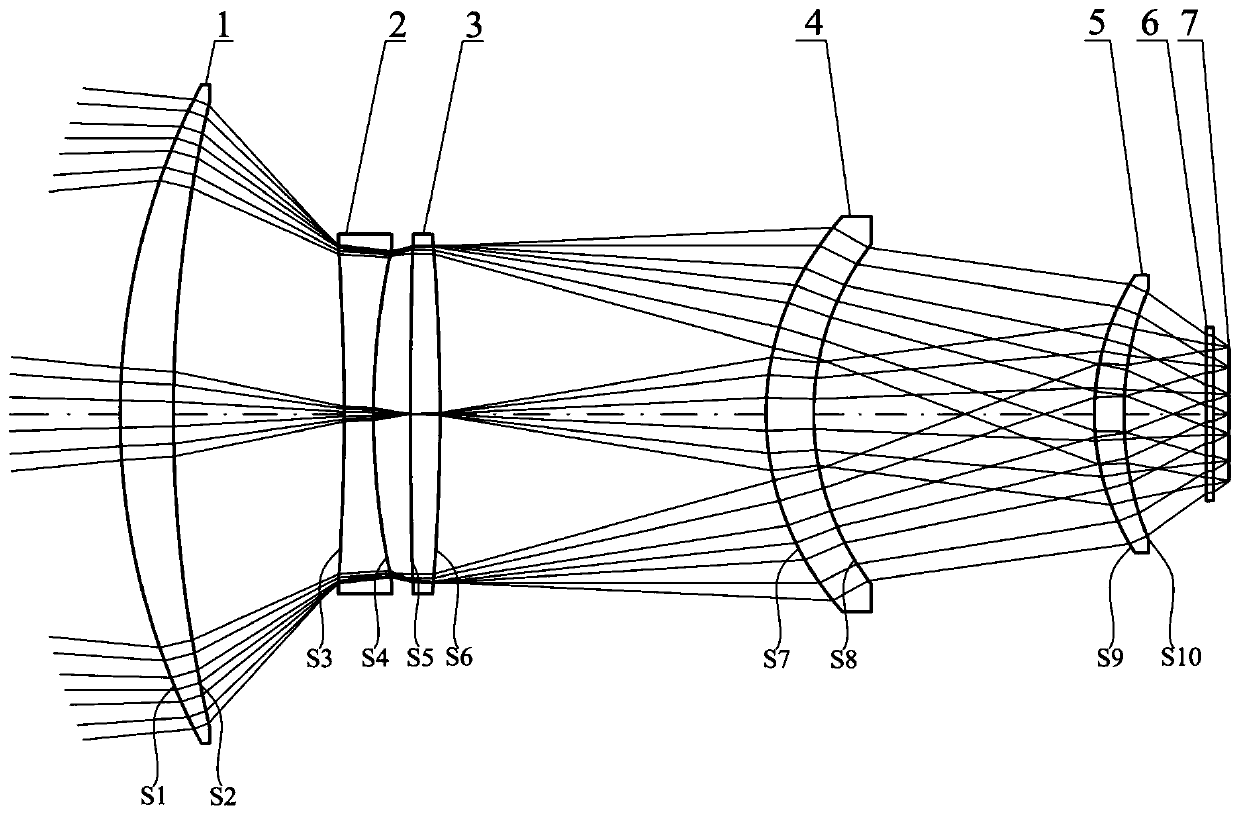
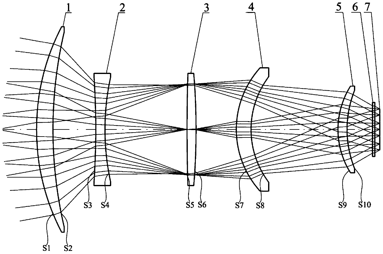
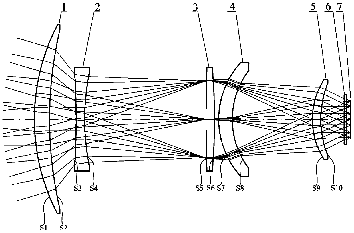

Image

  • Large-target-surface miniaturized non-refrigeration infrared continuous zooming optical system
  • Large-target-surface miniaturized non-refrigeration infrared continuous zooming optical system
  • Large-target-surface miniaturized non-refrigeration infrared continuous zooming optical system

Examples


specific Embodiment

[0061] The specific technical indicators realized by the system are shown in Table 1:

[0062]

[0063]

[0064] Table 1

[0065] Among them, F # (Optical system F number) The calculation formula is f / D, f is the focal length of the optical system, and D is the diameter of the entrance pupil.

[0066] The detailed data of the optical system of the present invention when the focal length is 30mm~90mm is shown in Table 2:

[0067]

[0068] Table 2 lists the surface type, radius of curvature, thickness, caliber, and material of each lens; among them, the unit of radius of curvature, thickness, and caliber of the lens is mm, the unit of weight is g, and the radius of curvature of spherical and aspheric surfaces refers to is the radius of curvature at the intersection of the lens surface and the optical axis. Among them, the "surface serial number" in Table 2 is counted along the direction of light propagation, such as the beam incident surface of the first meniscus pos...


PUM


Abstract

Disclosed is a large-target-surface miniaturized non-refrigeration infrared continuous zooming optical system. The large-target-surface miniaturized non-refrigeration infrared continuous zooming optical system comprises a first meniscus positive lens, a biconcave negative lens, a biconvex positive lens, a second meniscus positive lens, a third meniscus positive lens and a detector; the lens adoptsa refractive-diffractive hybrid system; through reasonable distribution of the focal power of each lens, the number of lenses of the system is reduced, the volume of the system is reduced, and the weight of the system is lowered; the zooming curve of the system is smooth and continuous, and the phenomenon of stagnation in the zooming process is effectively avoided; by adopting a mode of axially moving the third meniscus positive lens, the image plane off-focus compensation of the system in the temperature range of minus 40 DEG C to plus 60 DEG C and the off-focus compensation of the distancechange of an observed object are realized, the clear imaging of objects with different distances is ensured, and the system complication caused by the non-refrigeration design is avoided; and the large-target-surface miniaturized non-refrigeration infrared continuous zooming optical system fills the blank of a continuous zooming optical system which is adapted to a 1024 * 768 long-wave non-refrigeration type detector in China.

Description

technical field [0001] The invention relates to the field of large target surface uncooled infrared optical systems of airborne photoelectric equipment, in particular to a large target surface miniaturized uncooled infrared continuous zoom optical system. Background technique [0002] Uncooled infrared detectors have the advantages of low price, small size, light weight, low power consumption, and high reliability. Therefore, they are more and more widely used in military and civilian fields such as security monitoring and vehicles. [0003] At present, with the continuous progress of uncooled infrared technology, uncooled infrared detectors are also developing rapidly towards high performance and low cost, mainly used to meet the needs of military equipment with high sensitivity, high resolution, high frame frequency and The need to replace some cooled detectors; domestic uncooled infrared detectors have been mass-produced as 1024×768 long-wave uncooled infrared detectors w...

Claims


Application Information

Patent Timeline
IPC IPC(8): G02B15/173
CPCG02B15/173
Inventor 吴海清周桢刘志广
Owner 凯迈(洛阳)测控有限公司
Learn More