Image forming device, and image density stabilization control method
一种图像浓度、控制方法的技术,应用在应用电荷图形的电记录工艺、应用电荷图形的电记录工艺的设备、仪器等方向,能够解决图像浓度变化、调色剂静电附着力变化等问题,达到降低图像浓度变化的效果
- Summary
- Abstract
- Description
- Claims
- Application Information
AI Technical Summary
Problems solved by technology
Method used
Image
Examples
no. 1 approach 〕
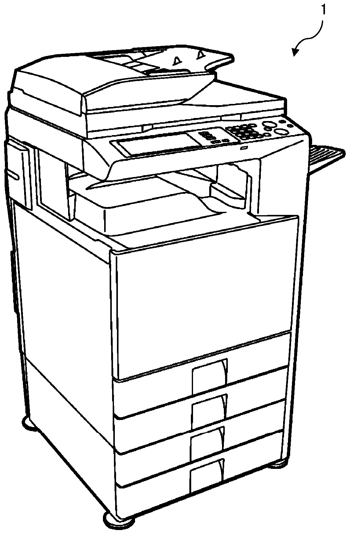
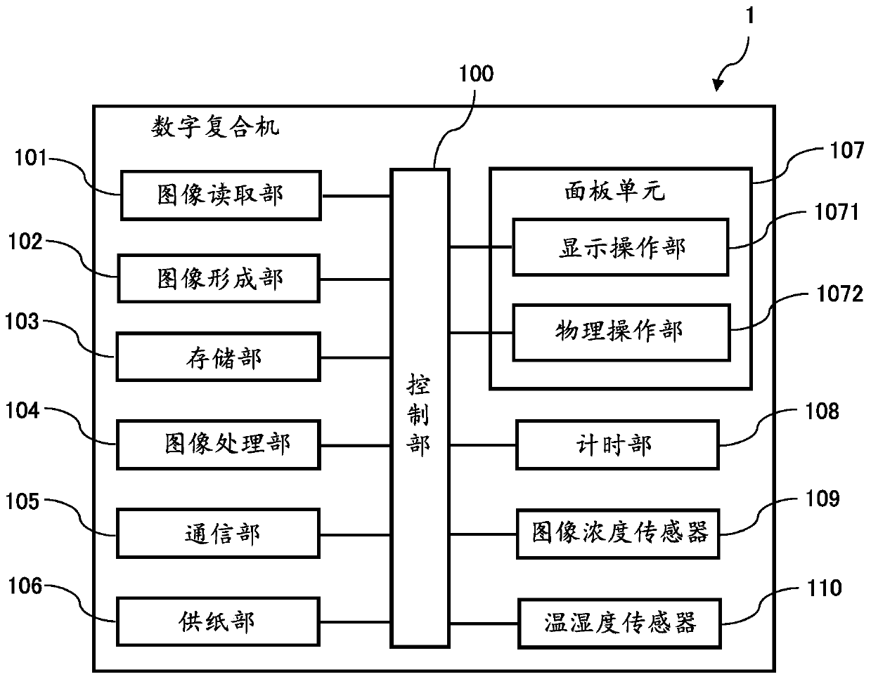
[0046] based on Figure 1 ~ Figure 3 Next, the digital multifunction peripheral 1 which is an embodiment of the image forming apparatus of the present invention will be described.
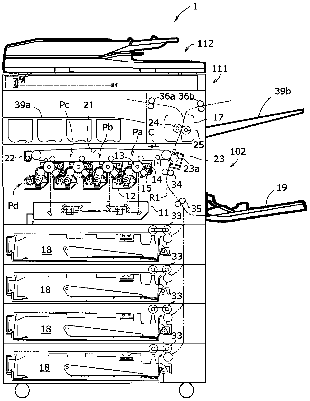
[0047] figure 1 It is a perspective view showing the appearance of a digital multifunction peripheral 1 which is an embodiment of the image forming apparatus of the present invention. figure 2 To represent figure 1 A cross-sectional view of the structure of the main body of the digital multifunction peripheral 1 shown.
[0048] The digital multifunction machine 1 is a device such as MFP (Multifunctional Peripheral: Multifunctional Peripheral) that performs digital processing of image data and has a copy function, a scanner function, and a fax function (refer to figure 1 ).
[0049] Such as figure 2 As shown, the digital multifunction peripheral 1 includes a document conveying device 112 that conveys a document to a reading unit, a document reading device 111 that reads a document, and an image forming un...
no. 2 approach 〕
[0162] Then, based on Figure 15 An example of image density stabilization control in the digital multifunction peripheral 1 according to the second embodiment will be described.
[0163] Figure 15 This is a graph showing the change in the charged potential of the photoreceptor drum 13 when printing is performed on two sheets of paper in the digital multifunction peripheral 1 according to the second embodiment and an example of its correction.
[0164] The change in the charged potential of the photosensitive drum 13 when printing on two sheets of paper is as Figure 15 As shown in the chart.
[0165] In addition, for simplification, the first sheet of paper is printed until 100 milliseconds, and the second sheet of paper is printed until 200 milliseconds.
[0166] in Figure 15 In the graph of, the horizontal axis represents the charging time (milliseconds), and the vertical axis represents the charging potential (-V) of the photosensitive drum 13. The closer the charged potential is...
no. 3 approach 〕
[0173] Then, based on Figure 16 An example of the image density stabilization control in the digital multifunction peripheral 1 according to the third embodiment will be described.
[0174] Figure 16 This is a graph showing an example of the change in the charged potential of each density portion of the photosensitive drum 13 in the digital multifunction peripheral 1 according to the third embodiment.
[0175] The change in the charged potential of the photosensitive drum 13 when the correction is applied without correction is as Figure 16 As shown in the chart.
[0176] in Figure 16 In the graph of, the horizontal axis represents the change in the charge potential of the photoreceptor drum 13 in the low-density portion, the middle-density portion, and the high-density portion, and the vertical axis represents the charge potential (V) of the photoreceptor drum 13.
[0177] In addition, in each concentration section, when the correction is not performed in order from the left, it in...
PUM
| Property | Measurement | Unit |
|---|---|---|
| humidity | aaaaa | aaaaa |
Abstract
Description
Claims
Application Information
 - R&D
- Intellectual Property
- Life Sciences
- Materials
- Tech Scout
- Unparalleled Data Quality
- Higher Quality Content
- 60% Fewer Hallucinations
Browse by: Latest US Patents, China's latest patents, Technical Efficacy Thesaurus, Application Domain, Technology Topic, Popular Technical Reports.
© 2025 PatSnap. All rights reserved.Legal|Privacy policy|Modern Slavery Act Transparency Statement|Sitemap|About US| Contact US: help@patsnap.com


