
A circuit board solder mask printing machine

A technology for circuit boards and printing machines, which is applied in the secondary treatment of printed circuits, coating of non-metallic protective layers, etc. It can solve the problems of wrong position of circuit board solder resistance, wrong position of screen printing traces, unqualified, etc., and achieve accurate The effect of improving the degree, increasing the friction, and ensuring the tension

Active Publication Date: 2020-12-08
嘉兴华竹电子有限公司
View PDF4 Cites 1 Cited by
  • Summary
  • Abstract
  • Description
  • Claims
  • Application Information

AI Technical Summary

Problems solved by technology

[0002] The circuit board solder mask is specifically to transfer the oil grinding to the circuit board to form a pattern consistent with the film. The solder mask is a protective film that can prevent bridging during welding and provide long-term insulation and chemical resistance. The ink is printed on the circuit board by screen, and the screen is clamped in a special screen frame, and stretched to meet the requirements. During the stretching process, the screen made of twill weave or nylon is used, although it is completely Stretch, but due to its structural characteristics, there will be a slight bulge in the middle, and the tension on both sides is the same, which is different from the tension in the middle. Materials with low softness such as twill weave and nylon are easy to produce Wrinkles, causing the position of the traces of the screen printing to be wrong, that is, the position of the solder mask of the circuit board is wrong, and it is unqualified

Method used

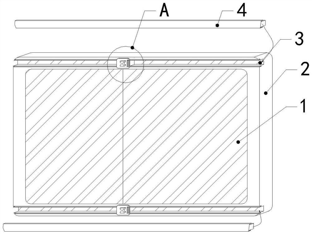

Image

  • A circuit board solder mask printing machine
  • A circuit board solder mask printing machine
  • A circuit board solder mask printing machine

Examples


Embodiment

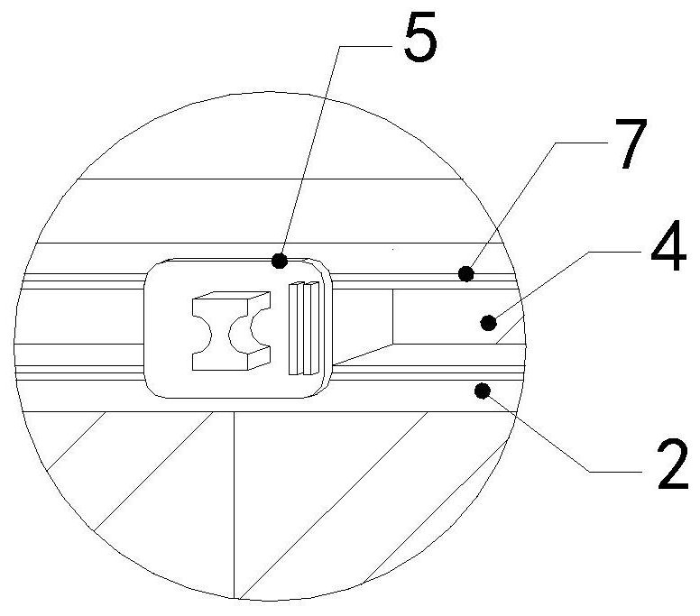
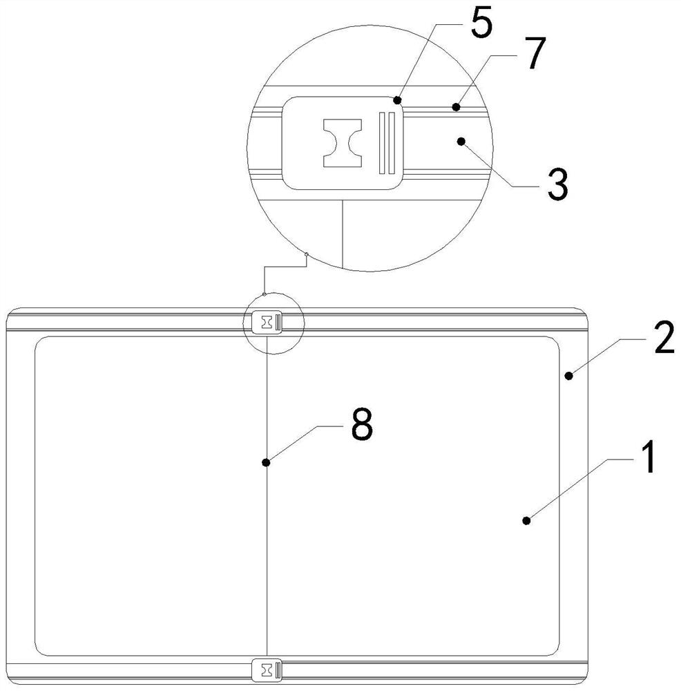
[0024] see Figure 1-Figure 5 , the present invention provides a circuit board solder resist printing machine, the structure of which consists of a body, a transmission device, a motor, an electromagnetic clutch, a reducer, a speed regulating mechanism, a screen printing frame, etc., and the structure of the screen printing frame includes a screen installation port 1, Frame body 2, pressing opening 3, embossing plate 4, and pressing slide block 5, the upper and lower sides of the frame body 2 are provided with mutually symmetrical pressing openings 3, and the pressing opening 3 is provided with a matching embossing plate 4 and a pressing slide block 5, the space in the middle of the frame body 2 is a screen installation opening 1, and the pressing slide block 5 matching therewith is installed in the pressing opening 3.

[0025] The pressing slider 5 is composed of a top plate 5-1, a sliding rod 5-2, and a bottom plate 5-3. The top plate 5-1 and the bottom plate 5-3 are vertica...


PUM


Abstract

The invention discloses a solder resist printing machine for a circuit board. The structure of a screen printing frame comprises a screen mounting opening, a frame body, a pressing opening, an imprinting plate and a pressing sliding block. Symmetrical pressing openings are formed in the upper side and the lower side of the frame body; an impressing plate and a flattening sliding block which are matched with the impressing opening are arranged on the impressing opening; the space in the middle of the frame body is a silk screen mounting opening; a flattening sliding block matched with the pressing opening is mounted in the pressing opening. According to the invention, the two flattening sliding blocks are used for smoothly sliding in the pressing opening provided with the silk screen, thereby preventing a screen made in an inclined weaved manner or made of a nylon material from creasing; by means of the design of the shifting block and the stopping block on the flattening sliding block,the stopping block is convenient for an operator to hold, the stopping block is arranged in front of the flattening sliding block for stopping and increasing friction when the operator holds the flattening sliding block, thereby further preventing an operation from being separated from the handle.

Description

technical field [0001] The invention relates to the field of printing machines, in particular to a circuit board solder resist printing machine. Background technique [0002] The circuit board solder mask is specifically to transfer the oil grinding to the circuit board to form a pattern consistent with the film. The solder mask is a protective film that can prevent bridging during welding and provide long-term insulation and chemical resistance. The ink is printed on the circuit board by screen, and the screen is clamped in a special screen frame, and stretched to meet the requirements. During the stretching process, the screen made of twill weave or nylon is used, although it is completely Stretch, but due to its structural characteristics, there will be a slight bulge in the middle, and the tension on both sides is the same, which is different from the tension in the middle. Materials with low softness such as twill weave and nylon are easy to produce Wrinkles, resulting...

Claims


Application Information

Patent Timeline
Patent Type & Authority Patents(China)
IPC IPC(8): H05K3/28
CPCH05K3/28
Inventor 林绥燕
Owner 嘉兴华竹电子有限公司
Learn More