
Electric pressure cooker with pressure relieving function

An electric pressure cooker and functional technology, applied in pressure cookers, household appliances, kitchen appliances, etc., can solve the problems of insignificant air-cooling effect, inability to quickly open the lid, and long waiting time.

Pending Publication Date: 2020-01-24
GREE ELECTRIC APPLIANCES INC
View PDF0 Cites 4 Cited by
  • Summary
  • Abstract
  • Description
  • Claims
  • Application Information

AI Technical Summary

Problems solved by technology

However, after the cooking work of the traditional electric pressure cooker is over, because there is high pressure in the pot, the user cannot immediately open the pot cover, but must open or press the pressure relief valve to exhaust and reduce the pressure, or let the food in the pot cool naturally, and wait until the pot Only when the pressure is reduced to normal pressure can the lid be opened to take out the food. Because the lid cannot be opened quickly after fast cooking and the food cannot be enjoyed immediately, resulting in a long waiting time, which brings great inconvenience to the user
[0003] In order to solve the technical problem that the traditional electric pressure cooker cannot be quickly opened, some technical solutions have been proposed in the industry: first, the cooling air blown by the cooling fan cools the inner pot or the lid after cooking, but in the actual application process It is found that the air cooling effect is not obvious, and the user still cannot open the pot cover quickly; the second is to actively discharge the gas in the pot through the exhaust device installed on the pot cover after cooking, and when the user opens or presses the pressure relief valve In the process of exhausting and depressurizing, if the food in the pot is liquid food, the liquid food in the pot is easily ejected from the exhaust port by high-pressure steam, causing danger to the user and polluting the inner and outer surfaces of the pot and the environment , causing cleaning problems

Method used


Image

  • Electric pressure cooker with pressure relieving function
  • Electric pressure cooker with pressure relieving function
  • Electric pressure cooker with pressure relieving function

Examples


Embodiment Construction

[0035] Features and exemplary embodiments of various aspects of the invention will be described in detail below. In the following detailed description, numerous specific details are set forth in order to provide a thorough understanding of the present invention. It will be apparent, however, to one skilled in the art that the present invention may be practiced without some of these specific details. The following description of the embodiments is only to provide a better understanding of the present invention by showing examples of the present invention. In the drawings and the following description, at least some well-known structures and techniques have not been shown in order to avoid unnecessarily obscuring the present invention; and, for clarity, the dimensions of some structures may have been exaggerated. Furthermore, the features, structures, or characteristics described hereinafter may be combined in any suitable manner in one or more embodiments.

[0036] The orient...


PUM


Abstract

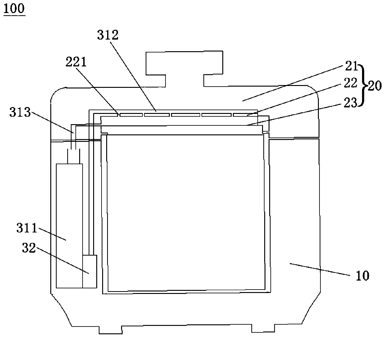
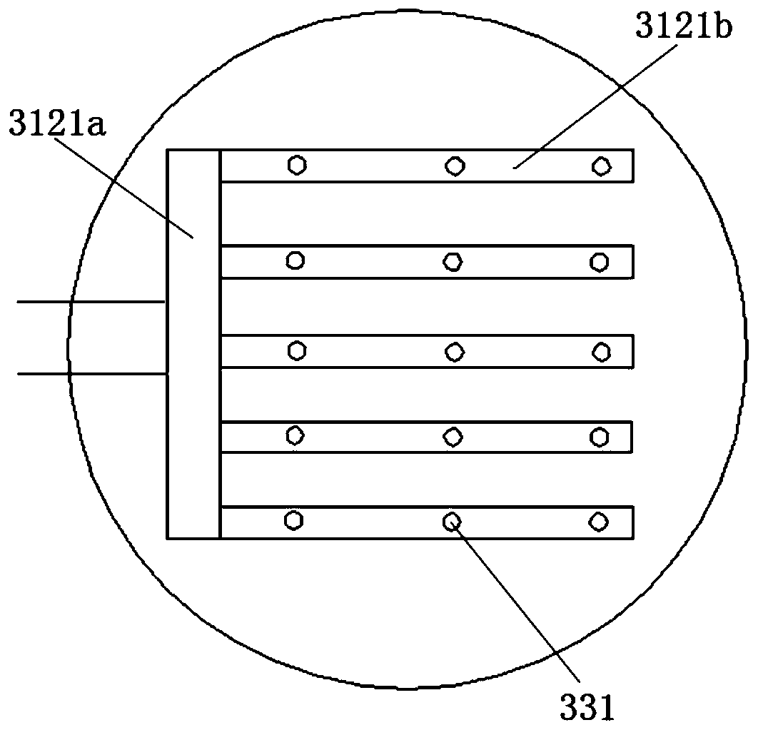
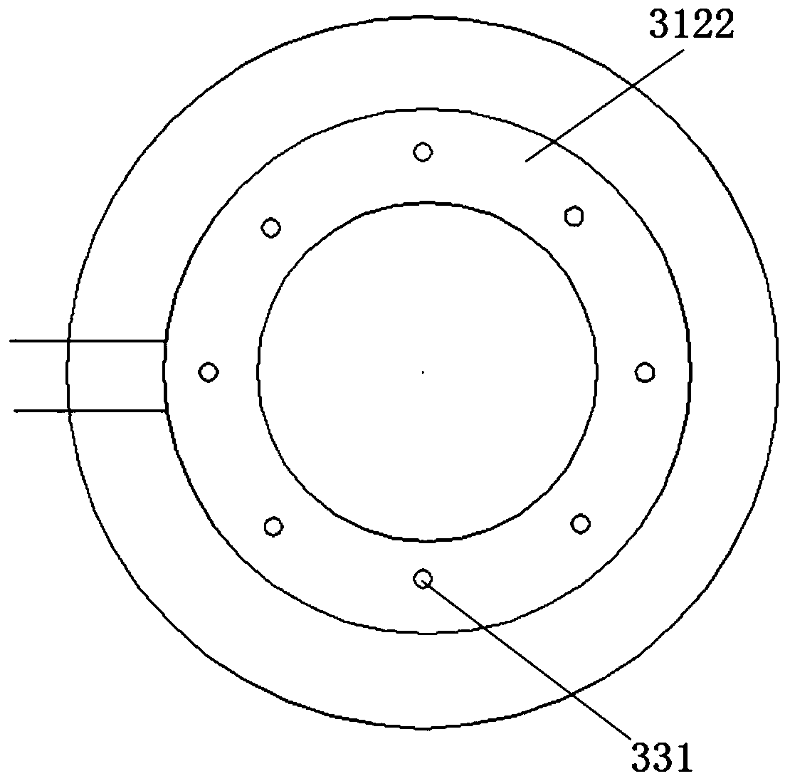
The invention relates to an electric pressure cooker with a pressure relieving function. The electric pressure cooker comprises a cooker body, a cooker cover and a jet flow impact cooling device, wherein the cooker cover is matched with the cooker body to be used; the jet flow impact cooling device comprises a circulation water path, a jet flow pump connected onto the circulation water path and aspraying device arranged in the pot cover; and the spraying device communicates with the circulation water path. The temperature in the cooker is fast lowered by using the jet flow impact cooling cooker cover; the reduction speed of the pressure in the cooker is further accelerated; the pressure relieving time is shortened; by using strong heat exchange capability of the jet flow impact cooling, the demanding quantity of the cooling water can be reduced; and the size of a water storage device and the size of the whole electric pressure cooker are reduced.

Description

technical field [0001] The invention relates to the technical field of electric pressure cookers, in particular to an electric pressure cooker with a pressure relief function. Background technique [0002] With the quickening pace of people's life, kitchen cooking utensils need to meet people's needs for quickness and convenience. The existing electric pressure cooker has many advantages such as fast cooking, high cooking temperature, less nutrient loss of cooking food, good food taste, power saving, etc., and has become an indispensable cooking utensil in the family kitchen. However, after the cooking work of the traditional electric pressure cooker is over, because there is high pressure in the pot, the user cannot immediately open the pot cover, but must open or press the pressure relief valve to exhaust and reduce the pressure, or let the food in the pot cool naturally, and wait until the pot After the pressure is reduced to normal pressure, the cover can be opened to t...

Claims


Application Information

Patent Timeline
IPC IPC(8): A47J27/092A47J27/08
CPCA47J27/08A47J27/092
Inventor 张健于博赵万东王训段智伟骆玉叶李叶松
Owner GREE ELECTRIC APPLIANCES INC
Learn More