
Parkinson's disease auxiliary muscle stretch device for neurology department

A neurology, stretching device technology, applied in passive exercise equipment, physical therapy and other directions, can solve the problem of low treatment effect of patients, and achieve the effect of easy rehabilitation, convenient use and simple structure

Inactive Publication Date: 2020-01-24
刘秀云
View PDF0 Cites 2 Cited by
  • Summary
  • Abstract
  • Description
  • Claims
  • Application Information

AI Technical Summary

Problems solved by technology

[0004] The purpose of the present invention is to solve the shortcomings of existing muscle stretching devices that can only stretch locally and have relatively low therapeutic effect on patients, and propose a muscle stretching device for assisting Parkinson's disease in neurology

Method used


Image

  • Parkinson's disease auxiliary muscle stretch device for neurology department
  • Parkinson's disease auxiliary muscle stretch device for neurology department
  • Parkinson's disease auxiliary muscle stretch device for neurology department

Examples


Embodiment 1

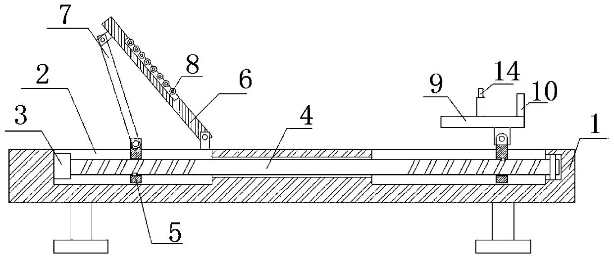
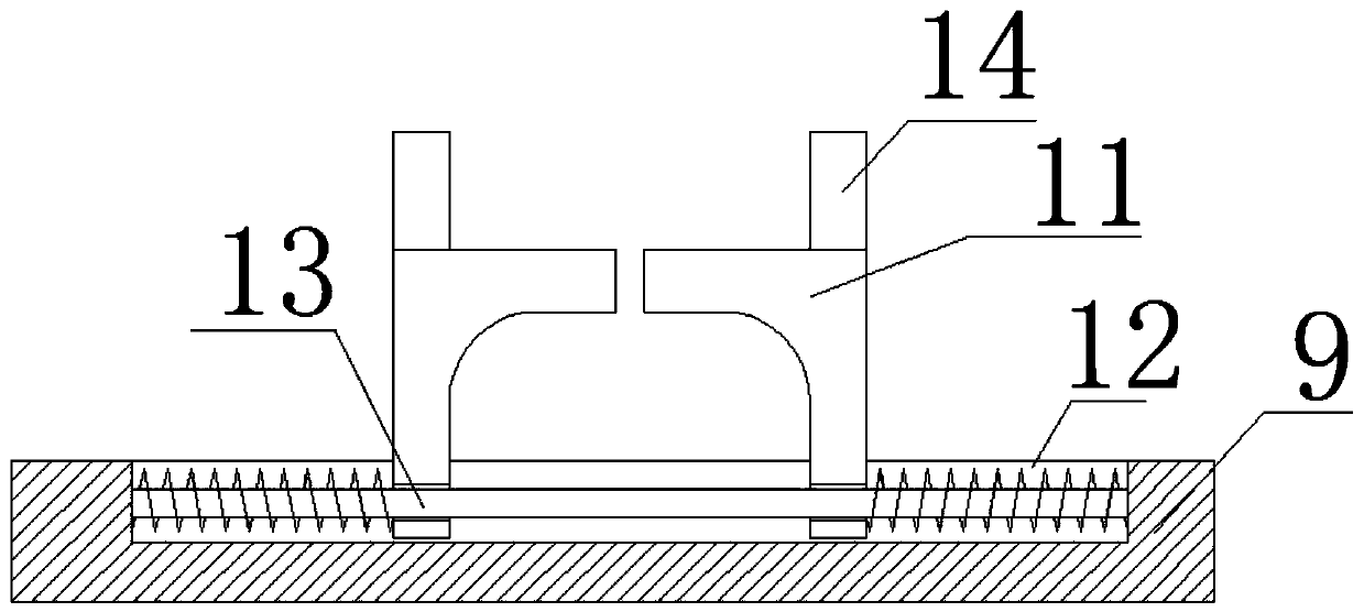
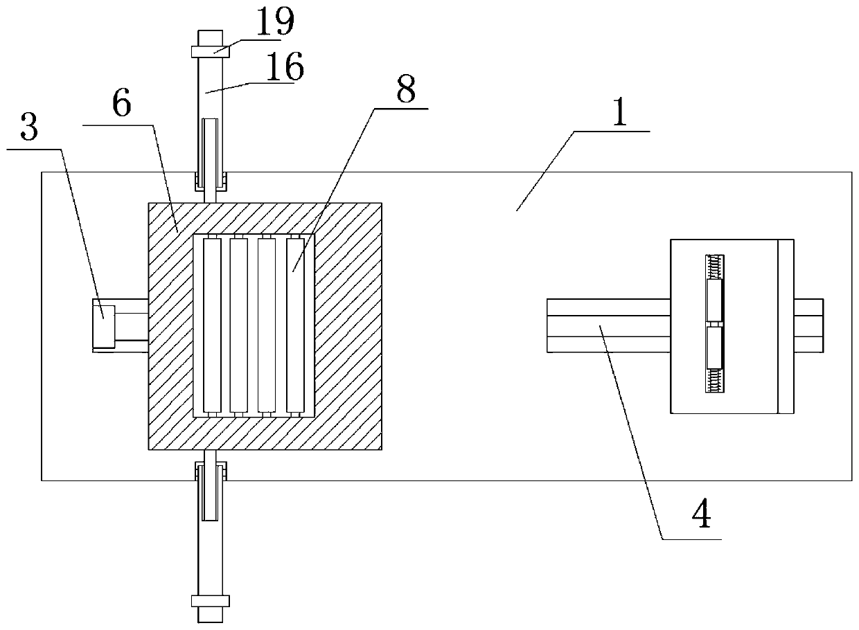
[0021] refer to Figure 1-4 , a muscle stretching device for Parkinson's disease in neurology, comprising a base 1, the top of the base 1 is provided with two symmetrically arranged sliding grooves 2, and the inner wall of one side of the sliding groove 2 in the two sliding grooves 2 A motor 3 is fixedly installed on the motor 3, and a rotating rod 4 is fixedly installed on the output shaft of the motor 3. Two symmetrically arranged moving plates 5 are slidably connected to the rotating rod 4. One of the moving plates 5 in the two moving plates 5 is connected in rotation. There is a hinged rod 7, the top of the base 1 is rotatably connected with a backing plate 6, the backing plate 6 is rotatably connected with the hinged rod 7, and the top of the backing plate 6 is rotatably connected with a plurality of rollers 8, and the other of the two moving plates 5 The top of the moving plate 5 is rotatably connected with a placement plate 9, and the top of the placement plate 9 is sli...

Embodiment 2

[0027] refer to Figure 1-4 , a muscle stretching device for Parkinson's disease in neurology, comprising a base 1, the top of the base 1 is provided with two symmetrically arranged sliding grooves 2, and the inner wall of one side of the sliding groove 2 in the two sliding grooves 2 A motor 3 is welded on the top, and a rotating rod 4 is welded on the output shaft of the motor 3. Two symmetrically arranged moving plates 5 are slidably connected to the rotating rod 4. One of the moving plates 5 in the two moving plates 5 is rotatably connected to a hinged joint. Rod 7, the top of the base 1 is rotatably connected with a backing plate 6, the backing plate 6 is rotatably connected with the hinged rod 7, and the top of the backing plate 6 is rotatably connected with a plurality of turning rollers 8, and the other moving plate in the two moving plates 5 The top of 5 is rotatably connected with a placement plate 9, and the top of the placement plate 9 is slidably connected with two...


PUM


Abstract

The invention belongs to the field of medical equipment, and especially relates to a Parkinson's disease auxiliary muscle stretch device for the neurology department. Existing muscle stretch device can only stretch locally and has a relatively low treatment effect on patients. In allusion to the above problem, the invention brings forward the following scheme: the device of the invention includesa base, the top of which is provided with two symmetrically arranged sliding grooves; a motor is fixedly mounted on the inner wall of one side of one sliding groove; a rotating rod is fixedly installed on an output shaft of the motor; two symmetrically-arranged shifting boards are slidably connected on the rotating rod; one of the two shifting boards is rotatably connected to a hinge rod; the topof the base is rotatably connected to a backup plate, which is rotatably connected with the hinge rod; and the top of the backup plate is rotatably connected with multiple rotating rollers. The deviceof the invention has a simple structure, is convenient to use, can effectively move and stretch the whole body of a patient, and is convenient for the recovery of patients.

Description

technical field [0001] The invention relates to the technical field of medical equipment, in particular to a muscle stretching device for assisting Parkinson's disease in neurology. Background technique [0002] Parkinson's disease is a common disease in neurology. The common clinical manifestations are muscle rigidity, slow movement, posture and gait disturbance, etc. In the treatment of Parkinson's disease, muscle stretching devices are often used for auxiliary treatment. [0003] The existing muscle stretching device can only stretch locally, and the therapeutic effect on patients is relatively low. Therefore, we propose a muscle stretching device for assisting Parkinson's disease in neurology. Contents of the invention [0004] The purpose of the present invention is to solve the shortcomings of existing muscle stretching devices that can only stretch locally and have relatively low therapeutic effect on patients, and propose a muscle stretching device for assisting Pa...

Claims


Application Information

Patent Timeline
IPC IPC(8): A61H1/02
CPCA61H1/0218A61H1/0222A61H1/0237A61H1/0274A61H2001/0233A61H2201/1207
Inventor 刘秀云闫瑞云高磊
Owner 刘秀云
Learn More