Horizontal type uniform-air-pressure pipe expansion device

A tube expansion device and air pressure technology, which is applied in the field of tube expansion of fin heat exchangers, can solve the problems of factory building area requirements, unfavorable expansion of heat pipes, and increase the defective rate of heat pipes, etc., to achieve a high degree of automation

Pending Publication Date: 2020-01-24
珠海华星智能技术有限公司
View PDF0 Cites 0 Cited by
  • Summary
  • Abstract
  • Description
  • Claims
  • Application Information

AI Technical Summary

Problems solved by technology

[0004] Since the expansion tube mandrel in the mechanical expansion method is in rigid contact with the inner wall of the heat dissipation tube, it is easy to cause damage to the inner wall of the heat dissipation tube, especially when the inner wall of the heat dissipation tube is processed into a threaded structure in order to increase the heat dissipation area, it is more likely to cause heat dissipation. The inner wall of the tube is damaged, which further increases the defective rate of the cooling tube
Moreover, during the mechanical expansion process, the wall thickness of the heat dissipation pipe will not become thinner with the expansion process. Therefore, when the diameter of the heat dissipation pipe increases, the length of the heat dissipation pipe will be compressed, that is, heat dissipation will occur. The phenomenon of tube shrinkage, the shrinkage rate is 3% to 5%, not only causes waste of materials, but also reduces the pass rate of fin heat exchangers
Furthermore, when mechanical tube expansion is used to complete the thermal tube expansion, it is necessary to use an expansion mandrel that is basically the same length as the thermal tube, which is not conducive to the expansion of thermal tubes of different specifications, and will increase the mechanical expansion device The overall size has higher requirements for the plant area

Method used


Image

  • Horizontal type uniform-air-pressure pipe expansion device
  • Horizontal type uniform-air-pressure pipe expansion device
  • Horizontal type uniform-air-pressure pipe expansion device

Examples


Embodiment Construction

[0040] The specific implementation manners according to the present invention will be described below in conjunction with the accompanying drawings.

[0041] In the following description, many specific details are set forth in order to fully understand the present invention, but the present invention can also be implemented in other ways different from those described here, therefore, the present invention is not limited to the specific embodiments disclosed below limit.

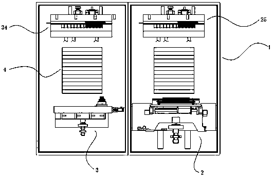
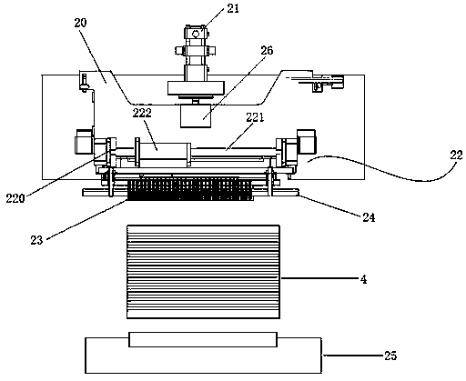
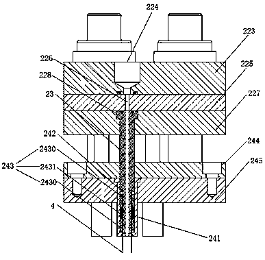
[0042] Such as Figure 1 to Figure 3 As shown, one embodiment of the present invention provides a horizontal air pressure uniform tube expansion device, including a workbench 1, a tube expansion unit 2 and a flaring unit 3, and the tube expansion unit 2 is arranged on the bearing surface of the workbench 1 and is connected with The bearing surfaces are parallel, and the expansion tube unit 2 can perform reciprocating linear motion along the axial direction of the heat dissipation tube 4; the flare unit 3 is...


PUM


Abstract

The invention provides a horizontal type uniform-air-pressure pipe expansion device which includes a workbench, a pipe expansion unit and a flaring unit. The pipe expansion unit is arranged on the workbench, and the flaring unit is arranged at the position, on one side of the pipe expansion unit, of the workbench; the pipe expansion unit includes a first base, a first mounting base, a nozzle and acompacting base, the first base is arranged on a bearing surface and is driven by a first driving unit to move in the axial direction of a heat dissipation pipe, the first mounting base is arranged on the first base, the nozzle is carried on the side, opposite to a pipe opening of the heat dissipation pipe, of the first mounting base, and the nozzle is driven by the first mounting base to achieveinsertion and extraction of the heat dissipation pipe; an inlet of the nozzle communicates with an outlet of an ultra-high pressure gas generator through a pipe; the compacting base is arranged on the side, close to the heat dissipation pipe, of the first mounting base; the compacting base is driven by a second driving unit to do reciprocating linear motion; a plurality of positioning holes are formed in the compacting base, a compacting sleeve is arranged in each positioning hole, and the compacting sleeves penetrate through the positioning holes to protrude out; and the inner walls of the compacting sleeves are provided with sealing pieces.

Description

technical field [0001] The invention relates to the technical field of tube expansion of finned heat exchangers, in particular to a horizontal air pressure uniform tube expansion device. Background technique [0002] Finned heat exchangers are generally composed of fins, radiating tubes densely distributed on the fins, and U-shaped tubes connected to adjacent radiating tubes. In order to improve the heat dissipation efficiency and stability of the finned heat exchanger, it is necessary to fully integrate the radiating tubes The fins are in contact to increase the heat exchange rate between the heat pipes and the fins. [0003] In order to achieve full contact between the heat dissipation tube and the fins, the tube wall of the heat dissipation tube is usually expanded radially by means of mechanical tube expansion, so that the heat dissipation tube forms a deformation zone and realizes expansion. [0004] Since the expansion tube mandrel in the mechanical expansion method i...

Claims


Application Information

Patent Timeline
Patent Type & Authority Applications(China)
IPC IPC(8): B21D39/08B21D39/00B21D26/033B21D41/02
CPCB21D26/033B21D39/00B21D39/08B21D41/02
Inventor 梁耀允陈雪彭岗举胡文斌
Owner 珠海华星智能技术有限公司
Why Eureka
Try Eureka