
Automatic deposition system and method

A kind of cladding and automatic technology, applied in the direction of metal material coating process, coating, etc., can solve the problems of waste of manpower and materials, backward control method of cladding, etc., achieve fast processing, reduce communication time, save cladding materials Effect

Active Publication Date: 2020-01-24
HARBIN KENENG CLADDING TECH
View PDF6 Cites 1 Cited by
  • Summary
  • Abstract
  • Description
  • Claims
  • Application Information

AI Technical Summary

Problems solved by technology

[0004] The purpose of the present invention is to provide an automatic cladding system in order to overcome the problems of backward cladding control methods and waste of manpower and materials

Method used


Image

  • Automatic deposition system and method
  • Automatic deposition system and method
  • Automatic deposition system and method

Examples


specific Embodiment approach 1

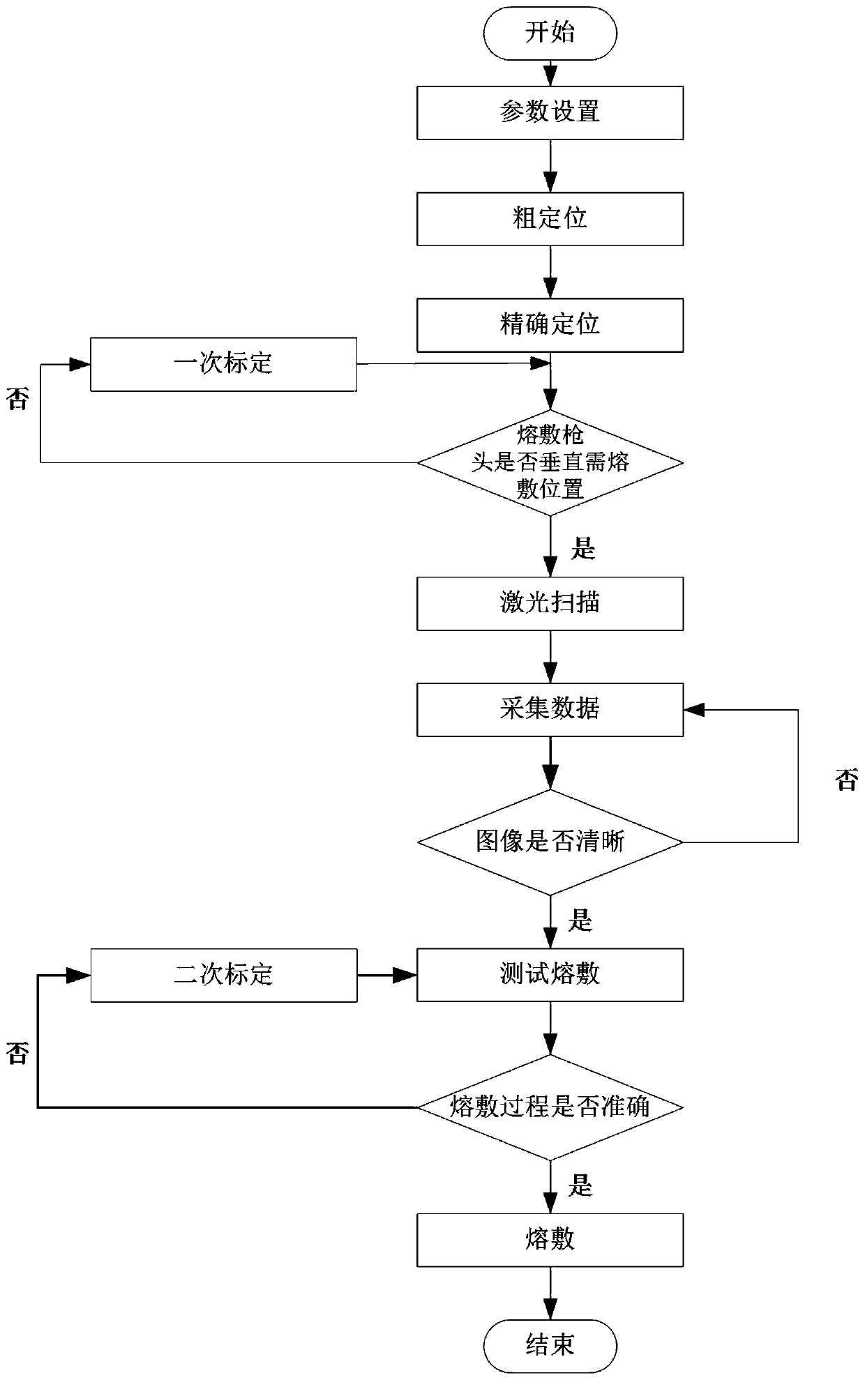
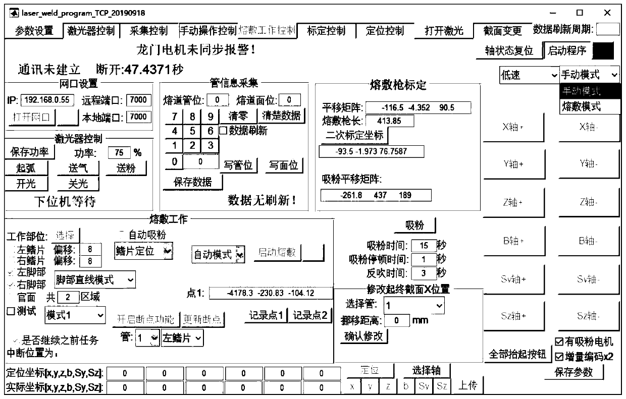
[0022] Embodiment 1: An automatic cladding system according to this embodiment, including a manual operation control module, a positioning control module, a laser scanning module and a cladding work control module;

[0023] The manual operation control module is used to input the direction key control signal, and the welding gun head moves to the welding position of the part to be welded according to the direction key control signal to realize rough positioning;

[0024] The positioning control module is connected with the manual operation control module. When the rough positioning is completed, the positioning control module is used to input the coordinates of the welding position of the parts to be welded and the adjustment angle of the welding gun head, and the welding gun head moves to the position to be welded. Position coordinates, and according to the adjustment angle, adjust the cladding gun head to be perpendicular to the position to be clad to complete precise positio...

specific Embodiment approach 2

[0036] Specific embodiment two: an automatic cladding method of this embodiment, the method includes the following steps:

[0037] Step 1: Input the manual moving speed signal and positioning speed signal of the cladding gun head;

[0038] Step 2: Input the direction key control signal, and the welding gun head moves to the welding position of the part to be welded according to the direction key control signal and manual movement speed signal, so as to realize rough positioning;

[0039] Step 3: Input the position coordinates of the parts to be welded and the adjustment angle of the welding gun head, the welding gun head moves to the coordinates of the welding position according to the positioning speed signal, and the welding gun head is adjusted to be vertical according to the adjustment angle Complete precise positioning at the position to be deposited;

[0040] Step 4: Use a laser scanner to scan the position of the part to be welded to obtain multiple discrete point maps...


PUM


Abstract

The invention relates to an automatic deposition system and method, and relates to a system and method for real-time movement control and precise positioning of a deposition gun head during water walldeposition. The system and method aim to solve the problem that a deposition control mode falls behind and manpower and materials are wasted. The automatic deposition system comprises a manual operation control module, a positioning control module, a laser scanning module and a deposition working control module, wherein the manual operation control module realizes coarse positioning, the positioning control module completes accurate positioning, the laser scanning module is connected with the positioning control module, when precise positioning is completed, the laser scanning module is usedfor scanning to-be-deposited position of a to-be-deposited part to obtain a plurality of discrete point graphs, according to the plurality of discrete point graphs, a to-be-deposited part topography drawing is constructed through fitting, the deposition working control module is connected with the laser scanning module and is used for extracting a deposition track from the to-be-deposited part topography drawing, so that the deposition gun head is used for deposition on the to-be-deposited position of the to-be-deposited part according to the deposition track.

Description

technical field [0001] The invention relates to the field of industrial cladding, in particular to a system and method for real-time control of the movement and precise positioning of a cladding gun head in water-cooled wall cladding. Background technique [0002] With the rapid development of modern industry, the requirements for the efficiency and accuracy of machines in many mechanized chemical fields are getting higher and higher. Many machines need to be operated under precise and accurate operations, so higher requirements are put forward for mechanical control methods. requirements. In industry, especially in the boiler industry, more and more surfacing welding deposition technology is used. Depositing a layer of wear-resistant or corrosion-resistant alloy layer on the surface of the workpiece can greatly increase its service life and save materials. good economy. [0003] However, this butt welding deposition technology requires high control accuracy of the deposit...

Claims


Application Information

Patent Timeline
IPC IPC(8): C23C24/10
CPCC23C24/103
Inventor 展乾聂万斌修洪伟曹学伟王坤吝忠良
Owner HARBIN KENENG CLADDING TECH
Learn More