Cyclone desander for wellhead of oil field

A cyclone type and desander technology, applied in the field of desander, can solve the problems of high cost and long time, and achieve the effect of good sand removal effect, good sand removal effect and increased practicability.

Active Publication Date: 2020-01-24
王立臣
View PDF5 Cites 4 Cited by
  • Summary
  • Abstract
  • Description
  • Claims
  • Application Information

AI Technical Summary

Problems solved by technology

[0004]However, when the above-mentioned technical solutions are actually used, there are still many shortcomings;
[0005] 1. Since the type selection of the cyclone desander must consider the amount of oil to be treated, the diameter of the external connection pipe, and the working pressure of the pipeline. Under the specific water volume and water pressure and other factors, it is necessary to select a device with a suitable model for desandering. Sand operation, and usually with the passage of production time, the oil output and oil hydraulic pressure of the oil well will inevitably change, and it is necessary to adjust the diameter of the external connection pipe or replace the desander with other specifications to adapt to the new oil pressure change. The method is time-consuming and expensive;

Method used


Image

  • Cyclone desander for wellhead of oil field
  • Cyclone desander for wellhead of oil field
  • Cyclone desander for wellhead of oil field

Examples


Embodiment 1

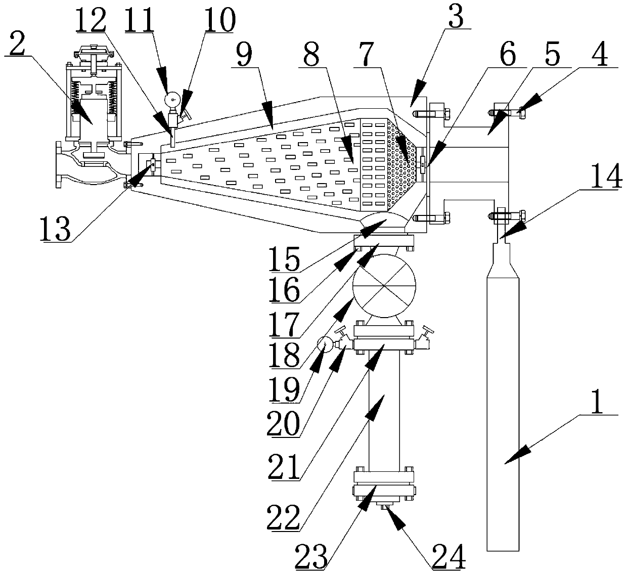
[0033] as attached Figure 1-4A cyclone desander for wellhead in an oil field is shown, which includes a bracket 1, a pressure regulating valve 2, a cylinder 3, a connecting screw 4, and a flange 5. The left end and the right end of the cylinder 3 have a liquid inlet and an outlet respectively. The liquid port, the pressure regulating valve 2, and the flange 5 are respectively fixedly installed on the liquid inlet and the liquid outlet of the cylinder 3 through the connecting screw 4. It is characterized in that: the connection between the pressure regulating valve 2, the flange 5 and the cylinder 3 A sealing ring 6 is provided, a connecting rod 14 is fixedly installed on the top of the bracket 1, and the top of the connecting rod 14 is fixedly installed under the flange 5, and the inside of the cylinder 3 is provided with a sand discharge cavity 9, and the inside of the cylinder 3 is fixed The sand discharge separation cylinder 8 is installed, the right end of the sand discha...

Embodiment 2

[0044] Concretely compared with embodiment 1: the appended reference manual Figure 7 As shown, one side of the cylinder 3 is provided with a liquid inlet, and the upper and lower ends of the cylinder 3 are respectively provided with a liquid outlet and a sand discharge port, and the sand discharge port of the cylinder 3 is provided with a communication hole 15, and the bottom of the cylinder 3 The end is preset with a screw, the screw at the bottom of the cylinder 3 has a matching connecting nut 16, the bottom of the cylinder 3 is fixedly installed with a connecting flange 17 through the connecting nut 16, and the bottom of the connecting flange 17 is fixedly installed with a valve 18 , the other end of the valve 18 is fixedly connected with a sand discharge flange 21, the sand discharge needle valve 20 is fixedly installed on both sides of the sand discharge flange 21, and the other end of the sand discharge needle valve 20 is provided with a sand discharge pressure gauge 19,...


PUM

PropertyMeasurementUnit
lengthaaaaaaaaaa
widthaaaaaaaaaa

Abstract

The invention discloses a cyclone desander for a wellhead of an oil field, and particularly relates to the field of desanders. The cyclone desander for the wellhead of the oil field comprises a support, a pressure regulating valve, a barrel, connecting screw rods and a flange. A liquid inlet and a liquid outlet are arranged at the two ends of the barrel separately, the pressure regulating valve and the flange are mounted in the liquid inlet and the liquid outlet of the barrel respectively, a communication hole is formed in the bottom of the barrel, and a connecting flange, a valve, a desandingflange and a sand setting body are installed at the bottom of the barrel through connecting nuts. A set of independent self-operated pressure regulating valve without power supply at the liquid inletis arranged, through pressure changes of oil liquid at the liquid inlet, small pressure changes of the oil liquid at the liquid inlet are amplified by intelligent control of the valve and fed back totwo pressure chambers of the valve, the opening degree of a valve port is adjusted, the cyclone desander can achieve the purpose of adjusting the pressure of the oil liquid behind the valve without replacing the pipe diameter of an external connecting pipe or replacing desanders of other specifications, and the practicability of the cyclone desander is greatly increased.

Description

technical field [0001] The invention relates to the technical field of desanders, and more specifically, the invention is a cyclone type desander for oilfield wellheads. Background technique [0002] At present, in wellhead oil production and oil testing operations in oil fields, crude oil is collected underground, transported to the ground, and then transported to the oil plant by pipelines or transport vehicles. Before this process, sand removal must be carried out through a desander, otherwise the crude oil The sand particles will wear the supporting equipment such as the transport vehicle; the ordinary desander currently used is easy to block the long sand discharge hole in the sand discharge separation cylinder, so that the impurities in the oil are not completely discharged, and the sand discharge effect is poor; In the sand cavity, impurities are easy to stay and need to be cleaned frequently, which is very inconvenient to use, wastes time and low work efficiency. ...

Claims


Application Information

Patent Timeline
Patent Type & Authority Applications(China)
IPC IPC(8): E21B43/34B01D21/26F16K17/30
CPCE21B43/34B01D21/267B01D21/0024F16K17/30
Inventor 王立臣王清伟张衡刘正孙长海李志赵丹刘洪俊孟剑锋罗海生庄秀禹颜廷虎邹宏刚宋晶鑫刘翠霞
Owner 王立臣
Why Eureka
Try Eureka