Oil-liquid vacuum automatic dehydration system

An oil and vacuum technology, applied in fluid pressure actuation system components, fluid pressure actuation devices, servo meter circuits, etc., can solve problems such as complexity, high labor costs, and difficulty in automatic control

Pending Publication Date: 2020-01-24
CHINA RAILWAY CONSTR HEAVY IND
View PDF2 Cites 0 Cited by
  • Summary
  • Abstract
  • Description
  • Claims
  • Application Information

AI Technical Summary

Problems solved by technology

However, the disadvantage of this patent is that the quality of the oil may be affected when the oil is in contact with dry air, and the structure of the packed tower used in this method is more complicated than that of the vacuum tank, and the air intake needs to be adjusted according to the oil flow, and Difficult to realize automatic control, high labor cost

Method used


Image

  • Oil-liquid vacuum automatic dehydration system

Examples


Embodiment Construction

[0023] The embodiments of the present invention will be described in detail below with reference to the accompanying drawings, but the present invention can be implemented in various ways defined and covered by the claims.

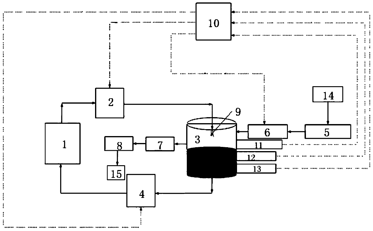
[0024] see figure 1 , an oil vacuum automatic dehydration system, including a circulation unit and a control unit for controlling the automatic operation of the circulation unit, the circulation unit includes an oil tank 1, an adjustable flow pump group one 2, an adjustable flow pump group two 4, a vacuum Tank 3, a proportional throttle valve 6 for adjusting the vacuum degree in the vacuum tank 3 and a vacuum pump 7 for providing negative pressure and discharging the vaporized water vapor in the vacuum tank 3, the oil outlet of the oil tank 1 The vacuum tank 3 is connected with the vacuum tank 3 through the adjustable flow pump group one 2, and the vacuum tank 3 is connected with the oil return port of the fuel tank 1 through the adjustable flow pump group...


PUM


Abstract

The invention provides an oil-liquid vacuum automatic dehydration system. The system comprises a circulation unit and a control unit which is used for controlling the circulation unit to operate automatically, wherein the circulation unit comprises an oil tank, an adjustable flow pump group I, an adjustable flow pump group II, a vacuum tank, a proportional throttle valve and a vacuum pump, the oiloutlet of the oil tank is connected with the vacuum tank through the adjustable flow pump group I, the vacuum tank is connected with the oil return port of the oil tank through the adjustable flow pump group II, the vacuum tank is connected with an air outlet through the vacuum pump, an air inlet is connected with the vacuum tank through the proportional throttle valve, a vacuum degree sensor anda temperature sensor are arranged in the vacuum tank, and the mutual matching of the vacuum degree and the water vapor temperature in the vacuum tank is achieved through cooperation of the vacuum degree sensor and the temperature sensor as well as the proportional throttle valve. The automatic dehydration system is high in oil-liquid separation efficiency, low in moisture content of the treated oil liquid, high in automation degree and high in efficiency.

Description

technical field [0001] The invention relates to the technical field of oil dehydration, in particular to an oil vacuum automatic dehydration system. Background technique [0002] Oil plays the role of energy transmission, anti-wear, system lubrication, anti-corrosion, anti-rust, cooling and so on in the hydraulic system. Oil pollutants mainly include solid particles, moisture, air and chlorides. In practice and research, one of the main reasons for the deterioration of oil performance is water entering the oil. Water pollution will cause deterioration of oil performance and lead to wear of components. [0003] In the prior art, Patent No. CN109642597A discloses a hydraulic mechanism for degassing and dehydrating hydraulic oil. Specifically, the liquid to be degassed flows through the throttling part from the pressure source, so that the fluid flowing through the throttling The liquid volume at the flow point and the flow cross-section of the throttle point are matched to e...

Claims


Application Information

Patent Timeline
Patent Type & Authority Applications(China)
IPC IPC(8): F15B21/048F15B21/0427
CPCF15B21/04F15B21/0427F15B2211/62F15B2211/66F15B2211/80
Inventor 张明明王博李玉琴王超于新洋吴阳林李平材刘佩芝潘焱
Owner CHINA RAILWAY CONSTR HEAVY IND
Why Eureka
Try Eureka