Mask and method for detecting light leakage degree of photo-etching machine

A mask, lithography technology, applied in the detection of the light leakage degree of the lithography machine, can solve the problem that the light leakage degree of the lithography machine cannot be accurately obtained, etc.

Active Publication Date: 2020-01-24
HUA HONG SEMICON WUXI LTD
View PDF7 Cites 2 Cited by
  • Summary
  • Abstract
  • Description
  • Claims
  • Application Information

AI Technical Summary

Problems solved by technology

[0004] This application provides a mask and a method for detecting the light leakage degree of a lithography machine, which can s

Method used


Image

  • Mask and method for detecting light leakage degree of photo-etching machine
  • Mask and method for detecting light leakage degree of photo-etching machine
  • Mask and method for detecting light leakage degree of photo-etching machine

Examples


Embodiment Construction

[0045] The technical solutions in this application will be clearly and completely described below in conjunction with the accompanying drawings. Apparently, the described embodiments are part of the embodiments of this application, not all of them. Based on the embodiments in this application, all other embodiments obtained by persons of ordinary skill in the art without making creative efforts belong to the scope of protection of this application.

[0046] In the description of this application, it should be noted that the terms "center", "upper", "lower", "left", "right", "vertical", "horizontal", "inner", "outer" etc. The indicated orientation or positional relationship is based on the orientation or positional relationship shown in the drawings, and is only for the convenience of describing the present application and simplifying the description, rather than indicating or implying that the referred device or element must have a specific orientation, use a specific orientati...


PUM


Abstract

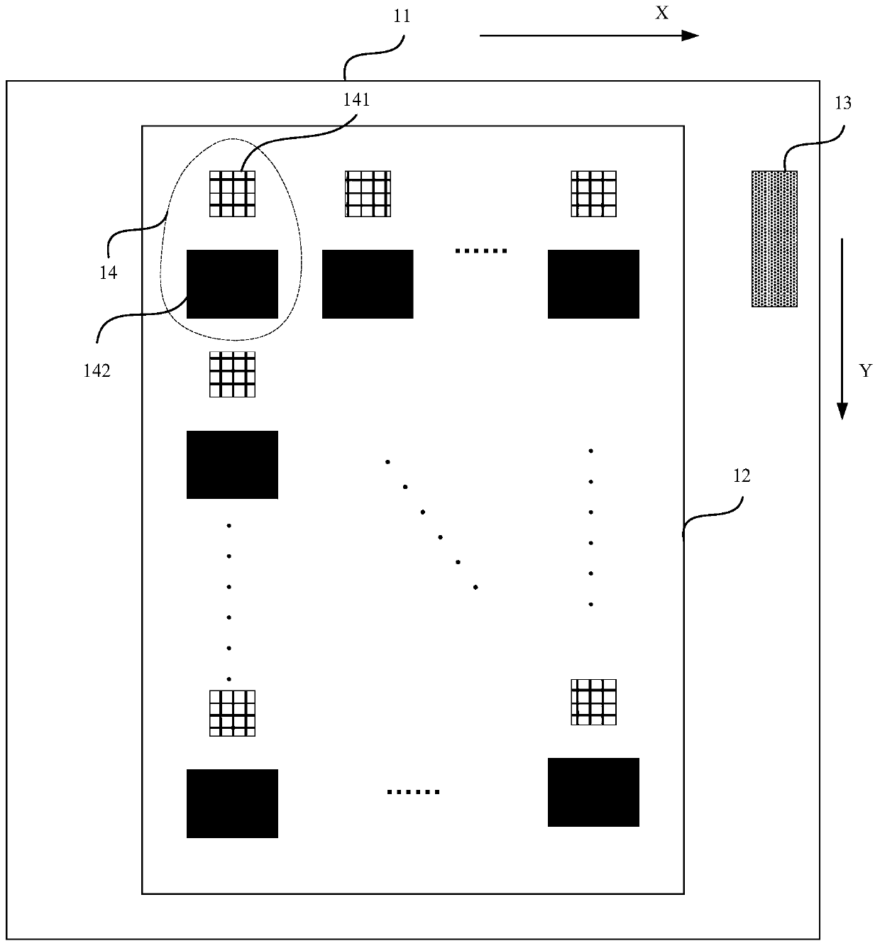
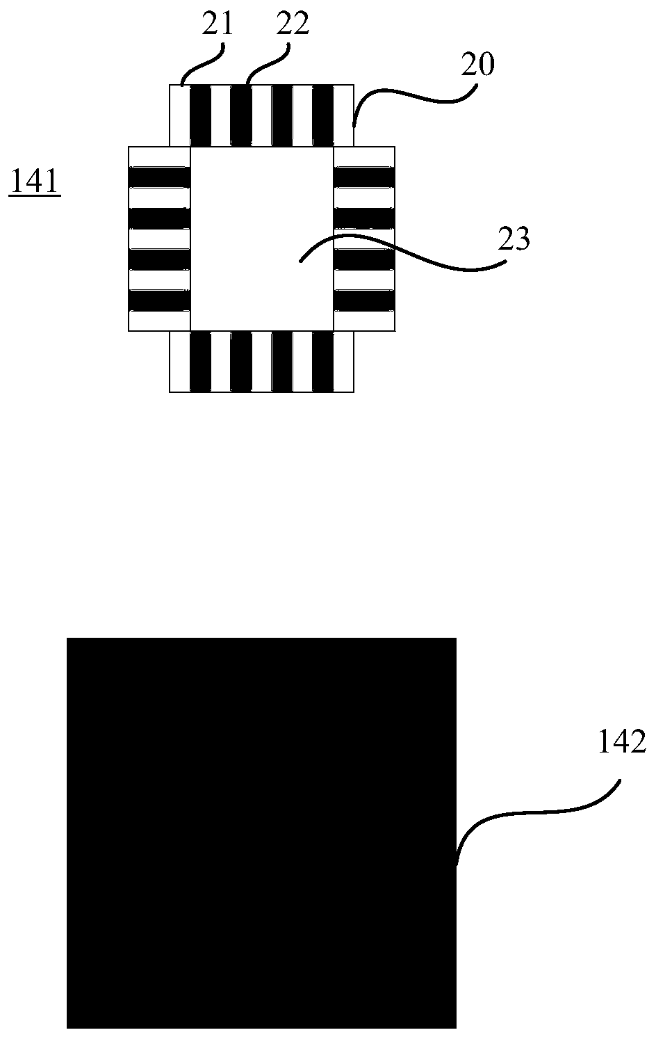
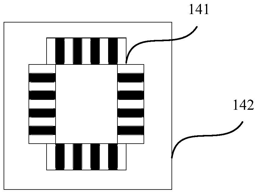
The invention discloses a mask and a method for detecting the light leakage degree of a photo-etching machine, and relates to the field of semiconductor manufacturing. The method comprises the following steps: providing a wafer coated with photoresist and a mask comprising a strip width test pattern and a full shading pattern; performing first exposure by using the mask; translating the mask to enable part of the strip width test pattern on the surface of the wafer to be completely covered by the full shading pattern on the mask; carrying out secondary exposure and development, the developed wafer surface comprising a repeated exposure strip width test pattern and an initial exposure strip width test pattern; and acquiring the strip width of the repeated exposure strip width test pattern and the strip width of the initial exposure strip width test pattern, and determining the light leakage degree of a photo-etching machine. The problem that the light leakage degree of a photo-etching machine cannot be rapidly and accurately obtained by an existing detection method is solved. The light leakage degree of a photo-etching machine can be quickly and accurately measured.

Description

technical field [0001] The present application relates to the field of semiconductor manufacturing, in particular to a mask plate and a method for detecting the degree of light leakage of a photolithography machine. Background technique [0002] The essence of photolithography is to copy the temporary circuit structure to the silicon wafer that will be etched and ion-implanted later. Modern lithography equipment is based on optical lithography, using an optical system to accurately project the pattern on the mask onto the silicon wafer coated with photoresist. A photolithography system basically includes a UV light source, an optical system, a projection mask consisting of chip patterns, an alignment system, and a silicon wafer covered with photosensitive photoresist. The two most common UV light sources currently used in optical lithography are mercury lamps and excimer lasers. [0003] For the ArF lithography machine, its wavelength is short and its energy is high, which...

Claims


Application Information

Patent Timeline
IPC IPC(8): G03F1/44G03F7/20
CPCG03F1/44G03F7/70625G03F7/70941Y02P70/50
Inventor 李玉华
Owner HUA HONG SEMICON WUXI LTD
Why Eureka
Try Eureka