Filling method of underfill

A technology of underfilling and filling method, which is applied in the manufacturing of electrical components, electric solid-state devices, semiconductor/solid-state devices, etc. Effect

Active Publication Date: 2020-01-24
SHANGHAI XIANFANG SEMICON CO LTD
View PDF8 Cites 2 Cited by
  • Summary
  • Abstract
  • Description
  • Claims
  • Application Information

AI Technical Summary

Problems solved by technology

However, in the process of filling the underfill into the gap between the chip and the organic substrate, the flow rate of the underfill under the chip has been considered to be the bottleneck of mass production in the underfill process, and the flow process will directly affect the reliability of the package. sex

Method used


Image

  • Filling method of underfill
  • Filling method of underfill
  • Filling method of underfill

Examples


Embodiment 1

[0040] This embodiment provides a method for filling an underfill, including:

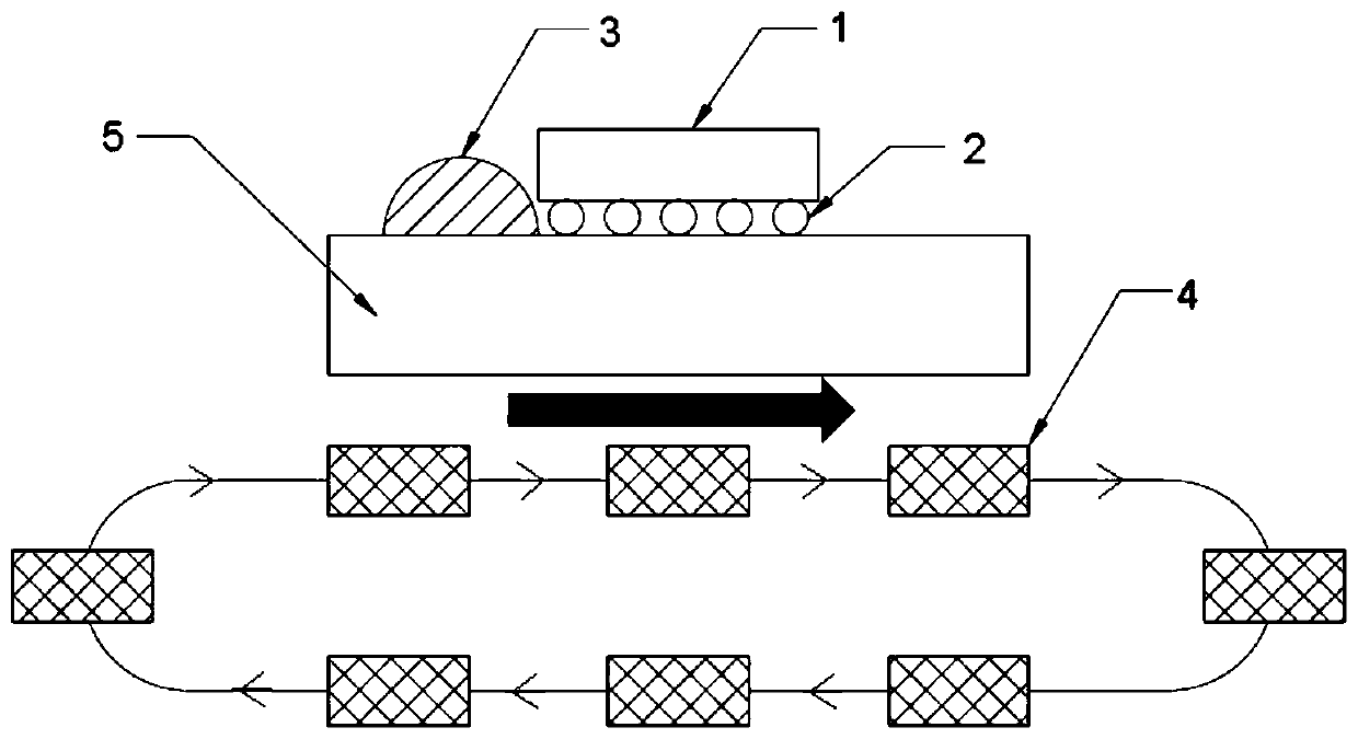
[0041] Add magnetic material to the underfill to form a composite filler 3, which is placed on one side of the chip 1, and the composite filler fills the gap between the substrate and the chip;

[0042] During the filling process, a magnet 4 is placed under the substrate 5 of the electronic packaging device and on the same side of the chip, and the magnet performs a circular movement in the area corresponding to the gap to be filled, and the trajectory is shown in figure 1 , the moving speed of the magnet is 0.5m / s, the magnet drives the magnetic material to move, and then drives the composite filler to flow to the other side of the chip, and fills the gap between the substrate and the chip to complete the filling process;

[0043] At 30°C, a filled electronic packaging device is formed after heating and curing;

[0044] Among them, the composite filler includes bisphenol A epoxy resin and magneti...

Embodiment 2

[0046] This embodiment provides a method for filling an underfill, including:

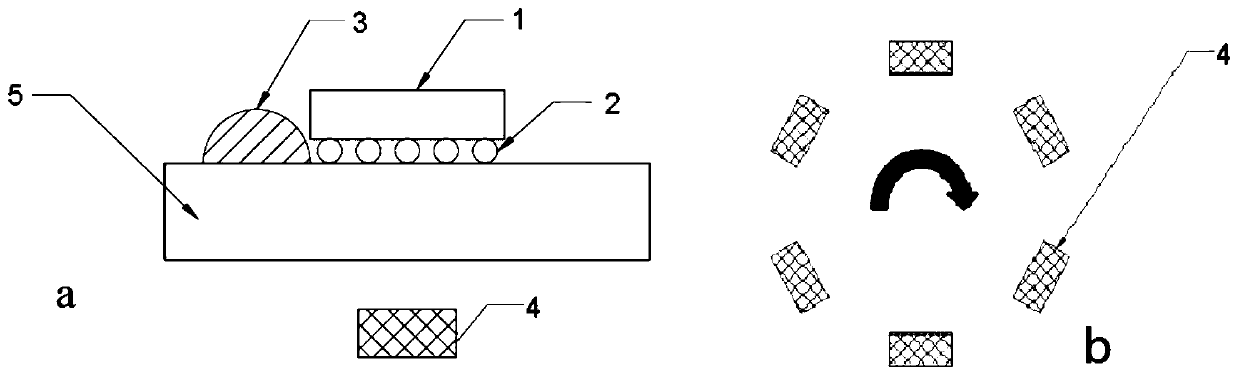
[0047] Add magnetic material to the underfill to form a composite filler 3, which is placed on one side of the chip 1, and the composite filler fills the gap between the substrate and the chip;

[0048] During the filling process, a magnet 4 is placed under the substrate 5 of the electronic packaging device and on the same side of the chip, and the magnet performs circular circular motion in the area corresponding to the gap to be filled. The motion track of the magnet is shown in figure 2As shown in middle b, the rotation speed of the magnet is 10 μm / s, and the diameter of the circular motion is 30 mm in length of the substrate. The magnet drives the magnetic material to move, and then drives the composite filling glue to flow to the other side of the chip, and the contact between the substrate and the chip is controlled. The gap is filled to complete the filling process;

[0049] At 100°C, afte...

Embodiment 3

[0052] This embodiment provides a method for filling an underfill, including:

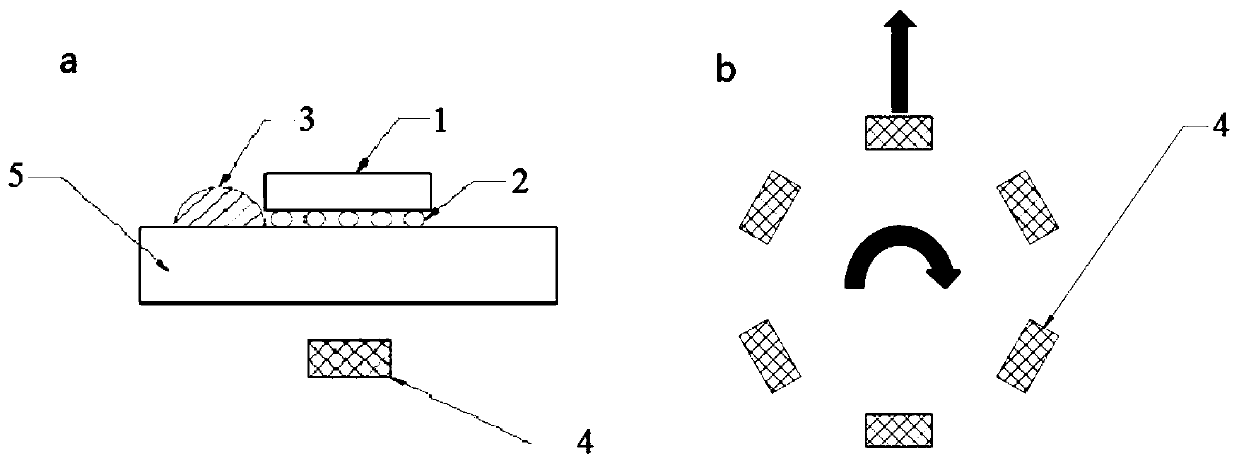
[0053] Add magnetic material to the underfill to form a composite filler 3, which is placed on one side of the chip 1, and the composite filler fills the gap between the substrate and the chip;

[0054] During the filling process, a magnet 4 is placed under the substrate 5 of the electronic packaging device and on the same side of the chip, and the magnet performs circular motion and centrifugal motion in the area corresponding to the filled gap, and the trajectory is shown in image 3 As shown in middle b, the speed of the circular motion of the magnet is 13 μm / s, and the speed of the centrifugal motion is 3 μm / s. The magnet starts to perform centrifugal motion and circular motion at the center of the substrate, and stops the centrifugal motion when the magnet moves centrifugally to the edge of the substrate. But keep doing the circular motion until the compound filler is completely filled. The m...


PUM


Abstract

The invention belongs to the technical field of semiconductor packaging and relates to a filling method of an underfill. The method comprises the step that: a magnetic material is added into the underfill, so that a composite fill adhesive can be formed. In the filling process, an external magnetic field drives the magnetic material so as to drive the composite filling adhesive to complete the filling process. According to the method, the magnetic material is driven by the external magnetic field, and continuous attraction can be provided for the underfill, so that the movement speed of the underfill is greatly increased, the problem of the incomplete filling of a large-size chip is reduced, filling time is greatly shortened, and production efficiency is improved.

Description

technical field [0001] The invention belongs to the technical field of semiconductor packaging, and in particular relates to a method for filling an underfill glue. Background technique [0002] With the rapid development of the electronic components industry, which is the basis of the electronic information industry, the miniaturization and high integration of electronic products has become a development trend. With the development trend of miniaturization, portability and functional diversification of electronic products, the package spacing of chip packages in electronic products is becoming smaller and smaller. Due to the small welding height, the shear force caused by mechanical stress makes the chip package It is very easy to break; at the same time, the coefficient of thermal expansion between the chip and the substrate, and between the substrate and the substrate is inconsistent, which will cause the solder joints to fall off or break when the chip is working, which ...

Claims


Application Information

Patent Timeline
Patent Type & Authority Applications(China)
IPC IPC(8): H01L21/56H01L21/67
CPCH01L21/56H01L21/67121H01L2224/16225
Inventor 陈立军徐友志曹立强
Owner SHANGHAI XIANFANG SEMICON CO LTD
Why Eureka
Try Eureka