Grain drying device

A grain drying and grain technology, applied in the direction of drying and preserving seeds, etc., can solve the problems of inability to realize effective monitoring and precise control, long drying time, and difficult to guarantee the quality after drying

Pending Publication Date: 2020-01-31
HUBEI KEYANG ENERGY SAVING EQUIP
View PDF0 Cites 4 Cited by
  • Summary
  • Abstract
  • Description
  • Claims
  • Application Information

AI Technical Summary

Problems solved by technology

[0005] 1. The high-temperature continuous dryer mainly deals with high-moisture corn in the northern region. For corn with a precipitation rate of no more than 20%, it can be dried to a safe storage of moisture at one time, and the drying efficiency is high. The residence time is long, and the entire drying process cannot be effectively monitored and accurately controlled. It belongs to extensive operation management, and the quality after drying is difficult to guarantee;
[0006] 2. The low-temperature circulation dryer mainly deals with high-moisture rice in the southern region. During operation, the temperature of the hot air and the precipitation rate of the grain are controlled to ensure the quality after drying. When the hot air passes through the grain, there is often an uneven distribution of the drying temperature field, which makes The drying efficiency is low. High-moisture grains need to be dried several times to achieve the required moisture. The drying time is too long. When the processing capacity is large, multiple dryers are required to be used in combination, which occupies a large area and requires construction investment. costly

Method used


Image

  • Grain drying device
  • Grain drying device
  • Grain drying device

Examples


Embodiment Construction

[0048] In order to enable those skilled in the art to better understand the technical solution of the present invention, the present invention will be described in detail below in conjunction with the accompanying drawings. The description in this part is only exemplary and explanatory, and should not have any limiting effect on the protection scope of the present invention. .

[0049] It should be noted that like numerals and letters denote similar items in the following figures, therefore, once an item is defined in one figure, it does not require further definition and explanation in subsequent figures.

[0050] It should be noted that the orientation or positional relationship indicated by the terms "center", "upper", "lower", "left", "right", "vertical", "horizontal", "inner" and "outer" are Based on the orientation or positional relationship shown in the drawings, or the orientation or positional relationship that the inventive product is usually placed in use, it is onl...


PUM


Abstract

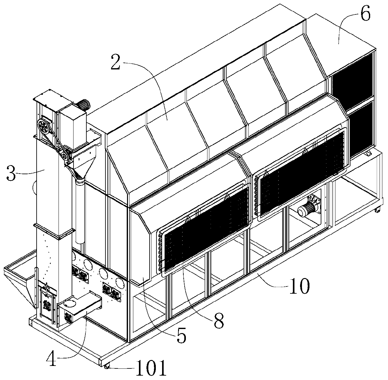
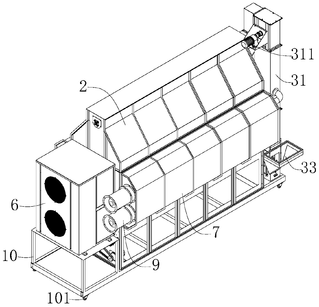
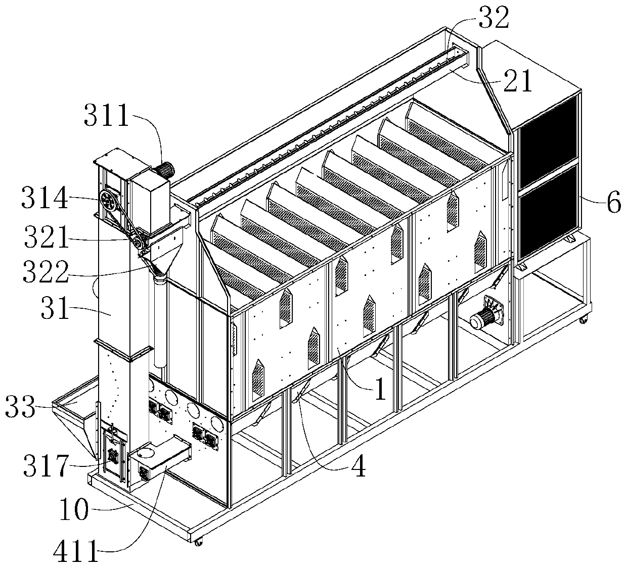
The invention relates to the field of grain drying, and discloses a grain drying device. The grain drying device comprises a drying box, a feeding mechanism, a discharging mechanism, an air inlet box,a heating device and an air outlet box. The drying box is used for carrying out hot drying on grain. Multiple drying layers are arranged inside the drying box. Each drying layer comprises a pluralityof air inlet angular boxes and a plurality of air outlet angular boxes, wherein the air inlet angular boxes and the air outlet angular boxes are arranged alternatively in the length direction of thedrying box horizontally. A cross flow type two-way ventilation structure is adopted for the drying box. Because the air inlet angular boxes and the air outlet angular boxes of each drying layer are arranged in parallel, the grain in the drying box is heated even; and the discharging mechanism is used for having control over the discharging speed of grain, then the drying time and the rate of moisture dropping of the grain in the drying box are taken under control. Compared with the prior art, the grain drying device not only can carry out continuous drying treatment on the grain with low moisture, but also can carry out circulating drying treatment on the grain with high moisture, and thereby being capable meeting various drying requirements of grains from different areas, with different contents of moisture, and of different breeds.

Description

technical field [0001] The invention relates to the field of grain drying, in particular to a grain drying device. Background technique [0002] In recent years, my country's grain mechanized drying has been rapidly developed and applied. Grain dryers have been widely used in grain storage, processing, distribution enterprises, cooperatives and large grain growers, and have effectively solved the problem of grain storage. The loss caused by mildew caused by too late to dry. [0003] Grain needs to consume a lot of fuel during the drying process. The existing dryers in my country are still mainly coal-fired and biomass pellet fuels, and they are equipped with coal-fired (biomass) hot air stoves. Generally, the thermal efficiency is not high, and the temperature of the hot air fluctuates greatly. The uneven distribution of the temperature field in the dryer will seriously affect the drying efficiency and the quality of the dried grain. In addition, fuel combustion produces a l...

Claims


Application Information

Patent Timeline
Patent Type & Authority Applications(China)
IPC IPC(8): A23B9/08
CPCA23B9/08
Inventor 李云克赵大富邓安福李云海刘涛魏文林胡兵兵
Owner HUBEI KEYANG ENERGY SAVING EQUIP
Why Eureka
Try Eureka