Liquid phase separation and purification device
A liquid phase separation and heating device technology, applied in separation methods, multi-effect/separative condensation, vapor condensation, etc., can solve the problems of difficult uniform diffusion of the target liquid and low liquid phase separation efficiency, and achieve improved condensation efficiency and high-efficiency separation. The effect of high purification and condensation efficiency
- Summary
- Abstract
- Description
- Claims
- Application Information
AI Technical Summary
Problems solved by technology
Method used
Image
Examples
Embodiment 1
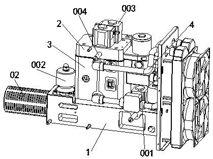
[0036] A kind of liquid phase separation and purification device of the present embodiment, such as figure 1 and figure 2 As shown, it includes an evaporative heating device 1 with a heating chamber and a condensing device 2 with a condensing chamber. The heating chamber of the evaporative heating device 1 communicates with the condensing chamber of the condensing device 2. An auxiliary Condensing device 4; the heating chamber is provided with a liquid filling valve 001 and an intake valve 002, and the condensation chamber is provided with a first separation valve 003 and a second separation valve 004.
[0037] For the convenience of illustration, it is assumed that the condensation temperature of the target liquid is A°, the condensation temperature of the impurity liquid is B°, and A°>B°.
[0038] The top of the evaporative heating device 1 is provided with a condensing device 2, the inside of the evaporative heating device 1 is provided with a heating chamber for evaporat...
Embodiment 2
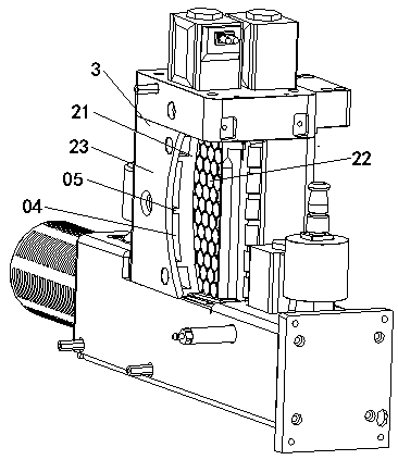
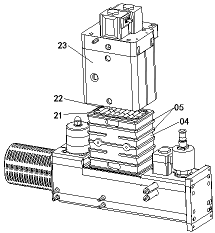
[0041] This embodiment is further optimized on the basis of embodiment 1, such as Figure 1-Figure 6 As shown, the condensing device 2 includes a condensing liner 21 with a condensing chamber inside. The condensing chamber of the condensing liner 21 is stacked with a number of condensing columns 22 in a honeycomb shape. The condensing columns 22 include coaxially arranged The first condensation column 201 and the second condensation column 202, one end of the first condensation column 201 and one end of the second condensation column 202 are connected by a spring 203, and the other end of the first condensation column 201 and the second condensation column The other end of 202 is in contact with the inner surface of the condensation liner 21 respectively.
[0042] The interior of the condensation liner 21 is a hollow condensation chamber for cooling the evaporating gas. The bottom of the condensing liner 21 is provided with a through hole or a connecting pipe for the evaporati...
Embodiment 3
[0052] This embodiment is further optimized on the basis of above-mentioned embodiment 1 or 2, such as Figure 1-Figure 3 As shown, a condensation shell 23 is also provided on the outside of the condensation liner 21, and an auxiliary condensation chamber 04 is arranged between the condensation shell 23 and the condensation liner 21; The water return port and the water inlet on one side communicate with the condensing end of the auxiliary condensing device 4 to form a condensing circuit.
[0053] An auxiliary condensation cavity 04 is formed between the outer surface of the condensation liner 21 and the inner surface of the condensation shell 23, and the upper and lower ends of the auxiliary condensation cavity 04 are respectively provided with a water return port and a water inlet through the condensation shell 23, and the water inlet and the return water port The pipe is connected with the condensing end of the auxiliary condensing device 4 to form a condensing circuit, and ...
PUM
 Abstract
Description
Claims
Application Information
 - R&D Engineer
- R&D Manager
- IP Professional
- Industry Leading Data Capabilities
- Powerful AI technology
- Patent DNA Extraction
Browse by: Latest US Patents, China's latest patents, Technical Efficacy Thesaurus, Application Domain, Technology Topic, Popular Technical Reports.
© 2024 PatSnap. All rights reserved.Legal|Privacy policy|Modern Slavery Act Transparency Statement|Sitemap|About US| Contact US: help@patsnap.com


