A non-interference laser shock peening method with two-robot linkage

A technology of laser shock strengthening and dual robots, which is applied in laser welding equipment, metal processing equipment, welding equipment, etc., can solve problems such as high process requirements, serious interference, and complex laser shock strengthening technology and equipment, so as to improve reliability and avoid Effects of interference problems, quality assurance and process stability

Active Publication Date: 2021-11-16
扬州镭奔激光科技有限公司
View PDF12 Cites 0 Cited by
  • Summary
  • Abstract
  • Description
  • Claims
  • Application Information

AI Technical Summary

Problems solved by technology

[0004] In view of the complex equipment, high process requirements and serious interference of laser shock peening technology, the existing technology needs to be further improved and perfected

Method used


Image

  • A non-interference laser shock peening method with two-robot linkage
  • A non-interference laser shock peening method with two-robot linkage
  • A non-interference laser shock peening method with two-robot linkage

Examples


Embodiment 1

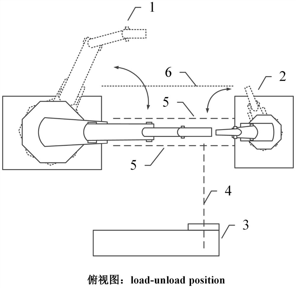
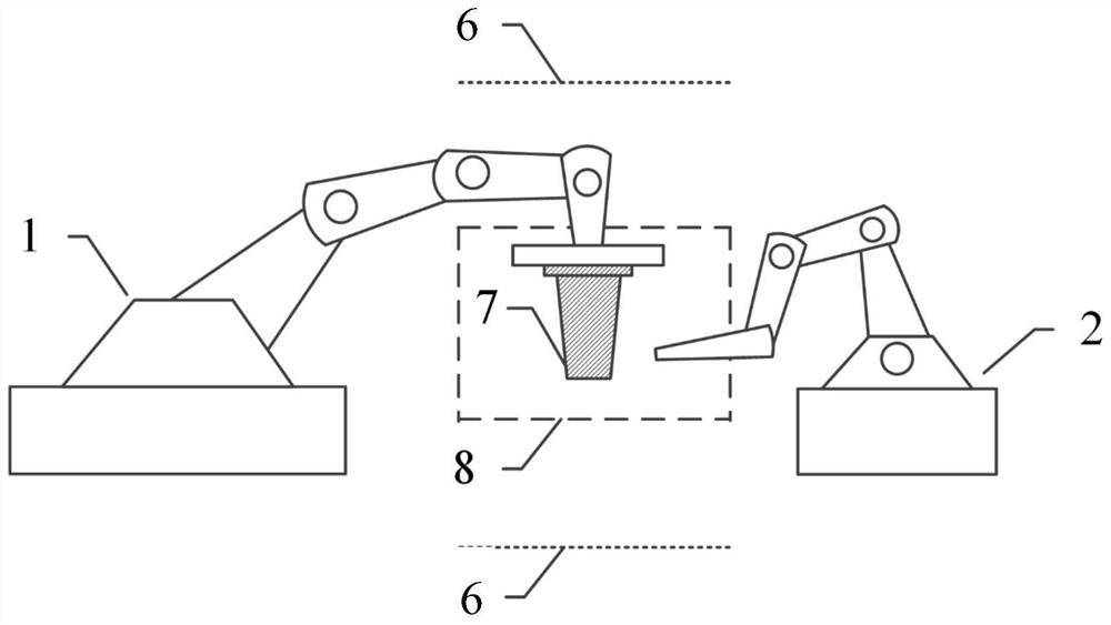
[0038] like Figure 1 to Figure 5 As shown, this embodiment discloses a double-robot linkage non-interference laser shock strengthening method, which uses two robots to respectively clamp and apply water to the parts to be processed, and specifically includes the following steps:

[0039] Step S1: Determine the processing area 8 according to the distance of the focal plane 5 of the pulsed laser beam 4; determine the safety plane 6 according to the external dimensions and process requirements of the part.

[0040] Specifically, the focal plane 5 in the step S1 is determined by the parameters of the optical path outside the laser system, and the focal plane 5 is the processing area 8 for laser shock strengthening. The safety plane 6 in the step S1 means that the movement of the robot in this area is safe and non-interfering.

[0041] As a preferred solution of the present invention, the safety plane 6 in the step S1 is set to a maximum size of 2 to 3 parts.

[0042] Step S2: S...

Embodiment 2

[0057] This embodiment is realized using two industrial robots with 6 degrees of freedom, in this instance:

[0058] A tool robot 1 with 6 degrees of freedom, with a load capacity of 10-400kg and a spatial repeat positioning accuracy of ±0.1mm, is designed with a special clamp for holding the blade 7 and fixing the fan blade 7 .

[0059] The other is a water coating robot 2 with 6 degrees of freedom, with a load capacity of 1 to 30 kg and a spatial repeatability positioning accuracy of ±0.1mm. It uses a customized internal pipeline to implement water coating;

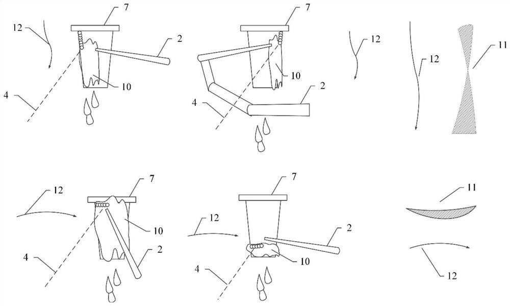
[0060] The 12-axis linkage is controlled by programming to complete the spatial coordinated movement, and realizes non-interference and equal-intensity laser shock strengthening on complex curved surfaces.

[0061] Non-interference includes two aspects, one is that there is no interference in the spatial movement between parts and robots, and the other is that there is no interference between the laser beam optical path...


PUM


Abstract

The invention discloses a double-robot linkage non-interference laser shock strengthening method. The method uses two 6-degree-of-freedom robots to program and control 12-axis linkage to complete spatial coordinated motion, and realizes non-interference and equal-intensity laser beams on complex curved surfaces. Impact strengthening. Non-interference includes two aspects, one is that there is no interference in the spatial movement between parts and robots, and the other is that there is no interference between the laser beam optical path and parts and robots. Equal intensity includes two aspects, one is that the focal length of the laser beam focused on the surface of the part is constant, and the other is that the incident angle of the laser beam in the area is constant. The laser shock peening method provided by the present invention has the advantages of high spatial freedom and good process stability, and is suitable for processing complex curved surface parts, such as fan blades, compressor blades, and the like.

Description

technical field [0001] The invention relates to the technical field of aviation manufacturing, in particular to a non-interference laser shock strengthening method for double robot linkage in the field of aviation manufacturing. Background technique [0002] Laser shock strengthening technology is one of the core manufacturing technologies of aero-engines in the United States. It has been successfully applied to fans of various military and civilian aircraft engines and compressor blades at all levels. It has effectively improved the ability to resist foreign object damage and high-cycle fatigue performance, and has achieved Huge success. Blade parts have complex curved surfaces and harsh surface accuracy, which have extremely high requirements for laser shock peening quality and process stability. Therefore, researchers at home and abroad have developed a series of equipment and methods to ensure that the shape and surface accuracy of the blade after strengthening can stil...

Claims


Application Information

Patent Timeline
Patent Type & Authority Patents(China)
IPC IPC(8): B23K26/352B23K26/356B23K26/00
CPCB23K26/00B23K26/352B23K26/356
Inventor 张峥吴瑞煜张永康
Owner 扬州镭奔激光科技有限公司
Why Eureka
Try Eureka