Welding method for exhaust casing of aircraft engine

An aero-engine and welding method technology, which is applied in welding equipment, automatic control devices, metal processing machinery parts, etc., can solve the problems of out-of-tolerance exhaust casing, large deformation, and low positioning accuracy, so as to save waste costs, Improved welding efficiency and stable quality

Active Publication Date: 2020-01-31
CHINA HANGFA GUIZHOU LIYANG AVIATION POWER CO LTD
View PDF7 Cites 2 Cited by
  • Summary
  • Abstract
  • Description
  • Claims
  • Application Information

AI Technical Summary

Problems solved by technology

[0003] The previous combination welding method of the exhaust casing was immature, the positioning accuracy was not high during assembly welding, and the deformation after assembly welding was large, resulting in frequent out-of-tolerance conditions of the exhaust casing after machining, which could not meet the design requirements and directly affected the aviation industry. Post engine assembly

Method used


Image

  • Welding method for exhaust casing of aircraft engine
  • Welding method for exhaust casing of aircraft engine
  • Welding method for exhaust casing of aircraft engine

Examples


Embodiment Construction

[0032] The technical solution of the present invention will be further described below in conjunction with the accompanying drawings, but the claimed protection scope is not limited to the description.

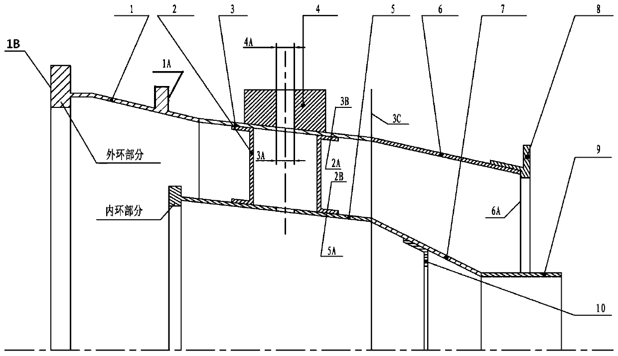
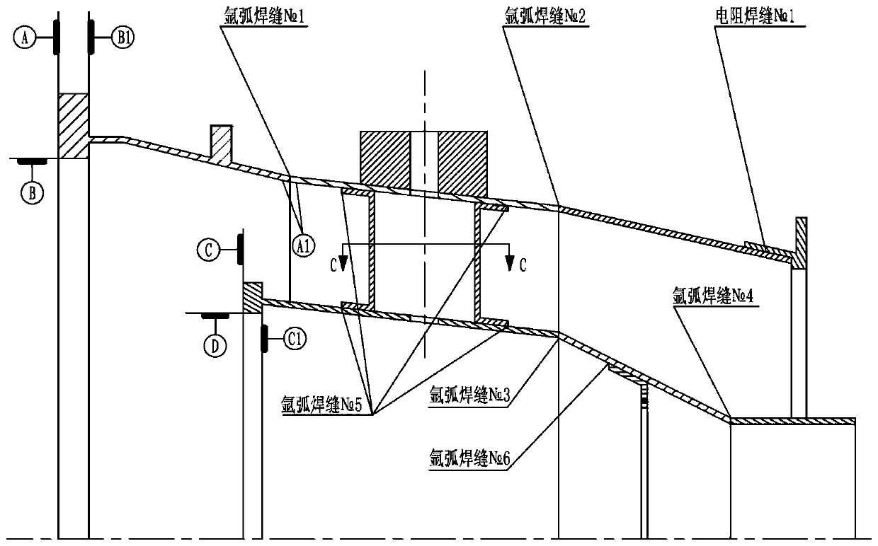
[0033] like figure 1 , The structure of the aero-engine exhaust casing is composed of an inner ring part, an outer ring part and a support plate. Part of the outer ring, the front mounting edge 1 of the outer ring is connected to the front section 3 of the cylinder by argon arc welding, the rear section 6 of the cylinder is connected to the front section 3 of the cylinder by argon arc welding, and the rear section 6 of the cylinder is connected to the rear installation edge 8 of the outer ring through Resistance welding connection; part of the inner ring, the inner ring mounting edge 5 is connected to the central beveled section 7 by argon arc welding, the central beveled section 7 is connected to the exhaust pipe 9 by argon arc welding, and the central beveled section 7 is co...


PUM


Abstract

The invention discloses a welding method for an exhaust casing of an aircraft engine. By means of reasonable arrangement of the welding sequence of an outer ring front mounting edge (1), a support plate (2), a front cylinder section (3), a mounting seat (4), an inner ring mounting edge (5), a rear cylinder section (6), a central cone oblique section (7), an outer ring rear mounting edge (8), an exhaust pipe (9) and a reinforcing ring (10) consisting an inner ring and an outer ring, a welding mode, an assembly sequence and standard selection, the problems of high processing accuracy requirement, many welding seams and compact space of the exhaust casing are solved, the welding quality is improved, and the following machining requirement is met.

Description

technical field [0001] The invention belongs to the technical field of aero-engine sheet welding manufacturing, in particular to a combined welding method for an aero-engine exhaust casing. Background technique [0002] like figure 1 As shown, it is a key component of an engine, the exhaust case, whose shape is the diameter The height is 270mm, and it is welded by multiple sheet metal parts, mounting edges and mounting seats. The processing accuracy of the parts is required to be high, the dimensional accuracy of the mounting edge is 0.03mm, and the shape and position tolerance accuracy is 0.01mm. The state of the components after welding is crucial to whether the later machining can meet the design requirements. [0003] The previous combination welding method of the exhaust casing was immature, the positioning accuracy was not high during assembly welding, and the deformation after assembly welding was large, resulting in frequent out-of-tolerance conditions of the exh...

Claims


Application Information

Patent Timeline
Patent Type & Authority Applications(China)
IPC IPC(8): B23K28/02B23Q15/00
CPCB23K28/02B23Q15/00
Inventor 余勇解为刚郑忠俊叶武郭飞张旭赵劲黎剑
Owner CHINA HANGFA GUIZHOU LIYANG AVIATION POWER CO LTD
Why Eureka
Try Eureka