Camshaft efficient machining intelligent lubrication cooling device and application method

A cooling device and machining technology, used in metal processing equipment, grinding/polishing safety devices, manufacturing tools, etc., can solve the problems of single type of lubricant, difficult operation, low work efficiency, etc., and achieve stable structural strength. Good flexibility and versatility, high modularity and intelligence, and improved processing quality and efficiency

Inactive Publication Date: 2020-01-31
JIAOZUO UNIV
View PDF7 Cites 3 Cited by
  • Summary
  • Abstract
  • Description
  • Claims
  • Application Information

AI Technical Summary

Problems solved by technology

[0002] At present, in the processing of camshafts, it is often necessary to use machine tools, grinding machines and other equipment to process workpieces. During the processing, in order to achieve lubrication and cooling of the processing surface, avoid damage to workpieces and tools caused by high temperatures during processing. At present, the main method is to directly spray lubricant or low-temperature air on the machining work surface through the hose and the nozzle, so as to achieve the purpose of cooling and lubricating. It is necessary, but during lubrication and cooling operations, the current lubrication and cooling system cannot assist in positioning the workpiece. In order to eliminate the defect of poor coaxiality accuracy of the camshaft workpiece caused by the feed of the tool and the gravity of the shaft workpiece, another It is necessary to add a supporting mechanism for auxiliary load-bearing positioning of the camshaft workpiece to the machining equipment, resulting in poor positioning stability and accuracy during the current camshaft machining, complex equipment structure, difficult operation and low work efficiency. On the other hand, the current lubrication and cooling When the system is running, the degree of automation, intelligence and versatility is insufficient, which leads to the need for each rack equipment to be equipped with independent lubrication and cooling systems, which seriously affects the convenience of equipment use and daily maintenance operations, and increases the number of components The cost and difficulty of equipment and storage management work, in addition, also lead to the current cooling and lubrication operations, the type of lubricant used is relatively single, and the control accuracy of the amount of use is poor, resulting in the current use of lubricants in camshaft processing to varying degrees The amount is far greater than the actual use, which increases the cost of lubricant use and causes serious waste of lubricant. It is also very easy to pollute the surface of the workpiece, machining equipment and the surrounding environment due to excessive use of lubricant, seriously Affects cost and quality of camshaft machining operations

Method used


Image

  • Camshaft efficient machining intelligent lubrication cooling device and application method
  • Camshaft efficient machining intelligent lubrication cooling device and application method
  • Camshaft efficient machining intelligent lubrication cooling device and application method

Examples


Embodiment Construction

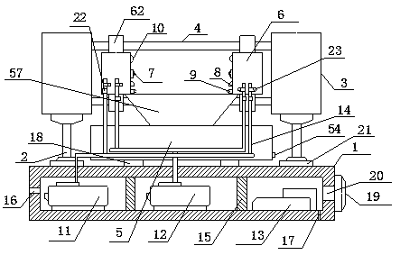
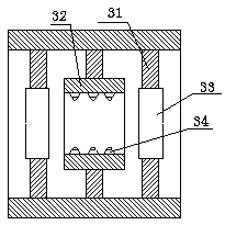
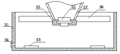
[0027] Such as Figure 1-4 An intelligent lubricating and cooling device for high-efficiency machining of camshafts is shown, which includes a bearing base 1, a lifting drive mechanism 2, a positioning seat 3, a guide rail 4, a collecting tank 5, a slider 6, a distance measuring device 7, and an infrared temperature measuring device. Device 8, lubricant spray port 9, jet air port 10, atomizing spray pump 11, jet pump 12 and control system 13, bearing base 1 is a closed cavity structure with a rectangular cross section, and its upper end surface is passed through a lifting drive mechanism 2 and the positioning seat 3 are connected to each other. There are two positioning seats 3 and they are symmetrically distributed on both sides of the bearing base 1, and the two positioning seats 3 are coaxially distributed and parallel to the upper end surface of the bearing base 1. Two ends are vertically connected to the front faces of the two positioning seats 3, and are parallel to the ...


PUM


Abstract

The invention relates to a camshaft efficient machining intelligent lubrication cooling device. The device comprises a bearing base, a lift driving mechanism, positioning bases, guide slide rails, slide blocks, distance measuring devices, infrared temperature measuring devices, lubricant spraying ports and jet air ports; the upper end surface of the bearing base is connected with the positioning bases through the lift driving mechanism; the two ends of the guide slide rail are connected with the front end surfaces of the two positioning bases; the slide blocks are slidingly connected with theguide slide rails; the distance measuring devices are distributed on the opposite side surfaces of the two slide blocks; and each slide block is uniformly distributed with at least two lubricant spraying ports, at least two jet air ports and one infrared temperature measuring device. An application method of the device comprises three steps of equipment assembly, workpiece positioning and machining operation. On the one hand, the device can effectively meet the demands of different machining equipment and different diameter types of camshaft machining mated operations; and on the other hand, the device can precisely realize efficient cooling lubrication operation for machining operation surfaces, workpiece surfaces and machining cutters.

Description

technical field [0001] The invention relates to an intelligent lubricating and cooling device for high-efficiency machining of a camshaft and a use method thereof, belonging to the technical field of machining equipment. Background technique [0002] At present, in the processing of camshafts, it is often necessary to use machine tools, grinding machines and other equipment to process workpieces. During the processing, in order to achieve lubrication and cooling of the processing surface, avoid damage to workpieces and tools caused by high temperatures during processing. At present, the main method is to directly spray lubricant or low-temperature air on the machining work surface through the hose and the nozzle, so as to achieve the purpose of cooling and lubricating. It is necessary, but during lubrication and cooling operations, the current lubrication and cooling system cannot assist in positioning the workpiece. In order to eliminate the defect of poor coaxiality accura...

Claims


Application Information

Patent Timeline
Patent Type & Authority Applications(China)
IPC IPC(8): B24B55/03
CPCB24B55/03
Inventor 王保华李春杰卢杉宋芳孙备王海燕
Owner JIAOZUO UNIV
Why Eureka
Try Eureka