
Compact and dual-redundancy absolute-type coder

An absolute encoder, dual-redundancy technology, applied in the field of encoders, can solve the problems of bloated system, increased cost, weak anti-electromagnetic interference ability, etc., and achieve the effects of small size, reduced system volume, and simple structure

Active Publication Date: 2020-01-31
连云港杰瑞电子有限公司
View PDF4 Cites 6 Cited by
  • Summary
  • Abstract
  • Description
  • Claims
  • Application Information

AI Technical Summary

Problems solved by technology

[0003] Common absolute encoders include magnetoelectric encoders and photoelectric encoders. Magnetoelectric encoders use Hall or reluctance principles, which have the advantage of being resistant to shock and vibration, but have weak anti-electromagnetic interference capabilities; while photoelectric encoders use photoelectric encoders. The conversion principle has the advantage of strong resistance to electromagnetic interference, but it is not resistant to shock and vibration
[0004] In important fields such as national defense and aerospace, redundant design needs to be considered in the application of encoders, that is, when one encoder output fails, it needs to seamlessly switch to the output of another encoder. The traditional method is to install on one shaft Two absolute encoders, although redundant design can be realized, but it will lead to bloated system and increased cost

Method used


Image

  • Compact and dual-redundancy absolute-type coder
  • Compact and dual-redundancy absolute-type coder
  • Compact and dual-redundancy absolute-type coder

Examples


Embodiment Construction

[0051] In order to make the purpose, technical solutions and advantages of the embodiments of the present invention clearer, the technical solutions in the embodiments of the present invention will be clearly and completely described below in conjunction with the drawings of the present invention. Obviously, the described embodiments are part of the present invention Examples, not all examples. Based on the embodiments of the present invention, all other embodiments obtained by persons of ordinary skill in the art without making creative efforts belong to the protection scope of the present invention.

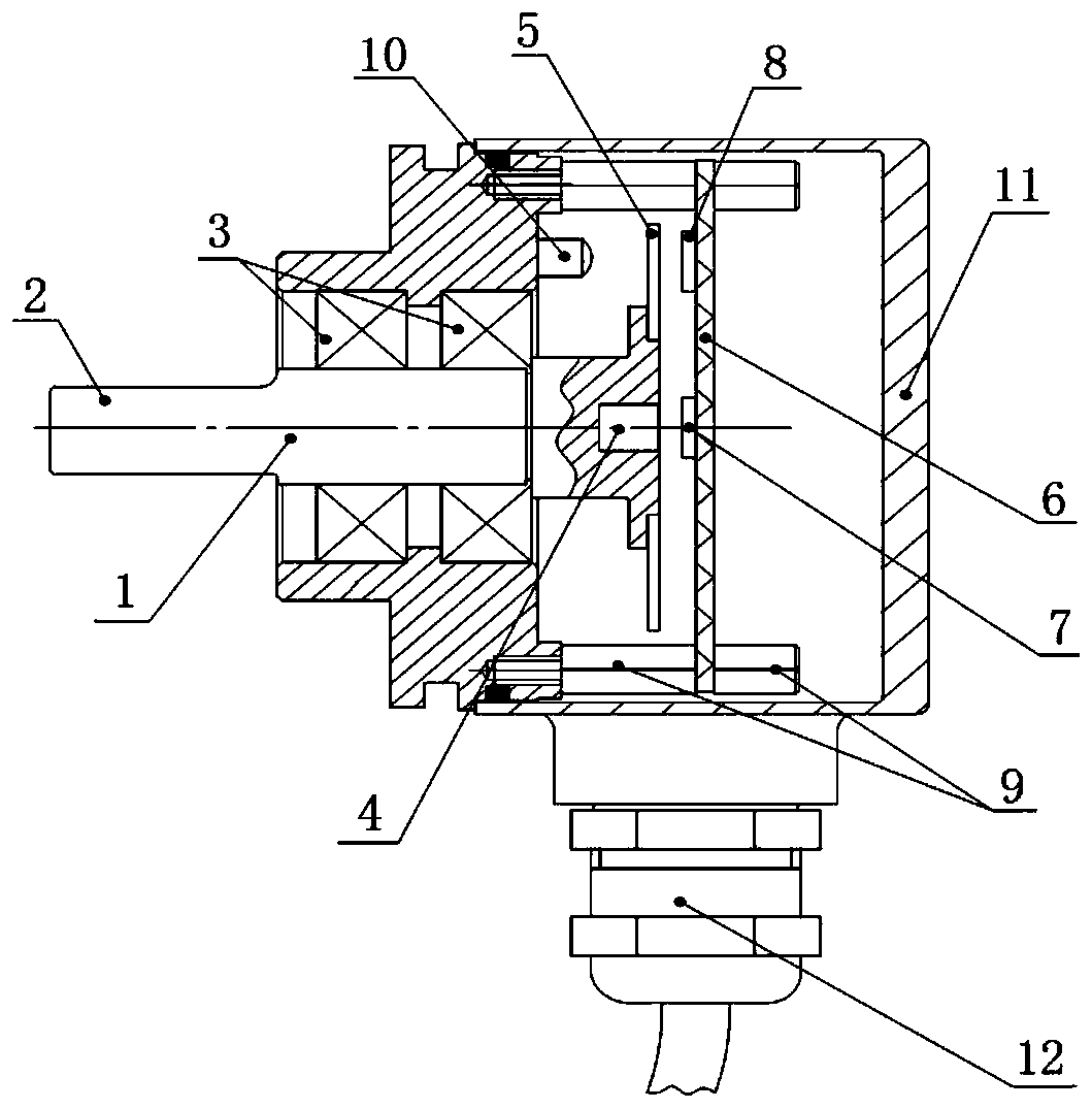
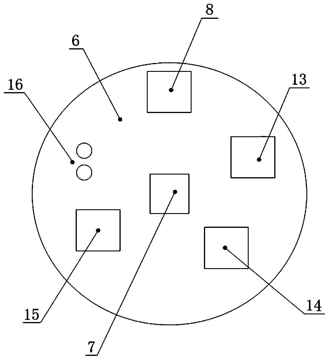
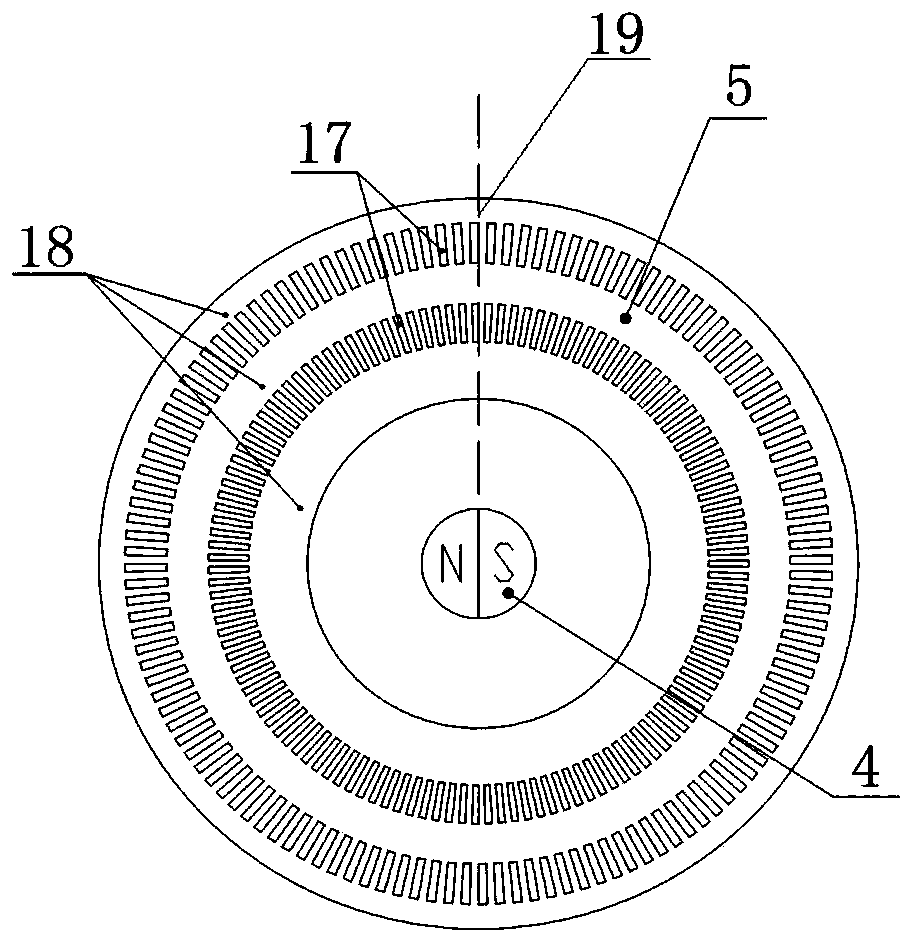
[0052] refer to Figure 1-13 , a compact double-redundant absolute encoder, the encoder includes a bearing support 1 and a rotating shaft 2 mounted on the bearing support 1 through a bearing 3, one end of the rotating shaft 2 runs through the bearing support 1 and is equipped with a magnet 4 and optical The code disc 5, the circuit board 6 that cooperates with the magnet 4 and...


PUM


Abstract

The invention relates to a compact and dual-redundancy absolute-type coder. The coder comprises a bearing support and a rotation shaft, wherein the rotation shaft is arranged on the bearing support bya bearing, a magnet and an optical coded disc are arranged at one end, penetrating through the bearing support, of the rotation shaft, a circuit board is further arranged on the bearing support and is matched with the magnet and the optical coded disc, a magnetic sensor, a photoelectric sensor and a microprocessor are arranged on the circuit board, the magnetic sensor is matched with the magnet,the photoelectric sensor is matched with the optical coded disc, the microprocessor is used for processing a signal, the circuit board is arranged at an outer side of the optical coded disc by a stud,and a photoelectric emission device is further arranged on the bearing support at an inner side of the optical coded disc and is matched with the photoelectric sensor. In the coder, a mode combininga single-antipode magnet and a bicode-channel coded disc is employed, redundancy absolute-type output of the coder can be achieved, and the volume of the coder also can be reduced; and meanwhile, thecoder also has the advantages of impact and vibration resistance and magnetic interference resistance.

Description

technical field [0001] The present invention relates to an encoder, in particular to a compact double-redundant absolute encoder, and also to a method for using the above-mentioned compact double-redundant absolute encoder. Background technique [0002] Absolute encoder is a sensor for measuring angle and displacement, and has been widely used in robot control, servo drive, wind power generation and national defense equipment and other fields. [0003] Common absolute encoders include magnetoelectric encoders and photoelectric encoders. Magnetoelectric encoders use Hall or reluctance principles, which have the advantage of being resistant to shock and vibration, but have weak anti-electromagnetic interference capabilities; while photoelectric encoders use photoelectric encoders. The conversion principle has the advantage of strong anti-electromagnetic interference ability, but it is not resistant to shock and vibration. [0004] In important fields such as national defense ...

Claims


Application Information

Patent Timeline
IPC IPC(8): G01D5/14
CPCG01D5/14
Inventor 石洪徐磊程亚博章帆高虎朱刘英穆如传张智沈孟龙
Owner 连云港杰瑞电子有限公司
Learn More