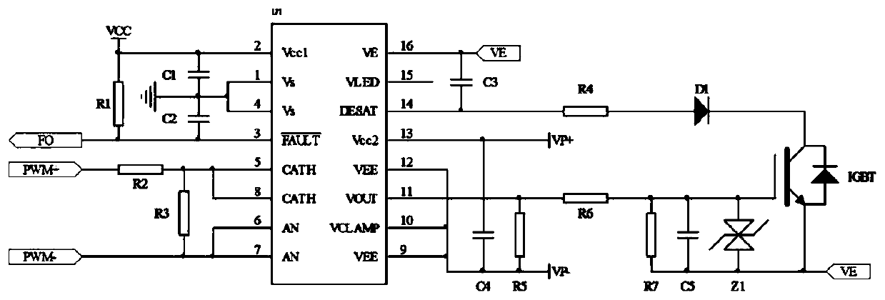
Driving and protecting circuit for inversion module
A technology of inverter module and protection circuit, applied in the field of inverter, can solve the problems of reducing product protection function, no protection of inverter module, and compressing product volume.
- Summary
- Abstract
- Description
- Claims
- Application Information
AI Technical Summary
Problems solved by technology
Method used
Image
Examples
Embodiment Construction
[0019] The technical solutions of the present invention will be further described below in conjunction with the accompanying drawings and through specific implementation methods.
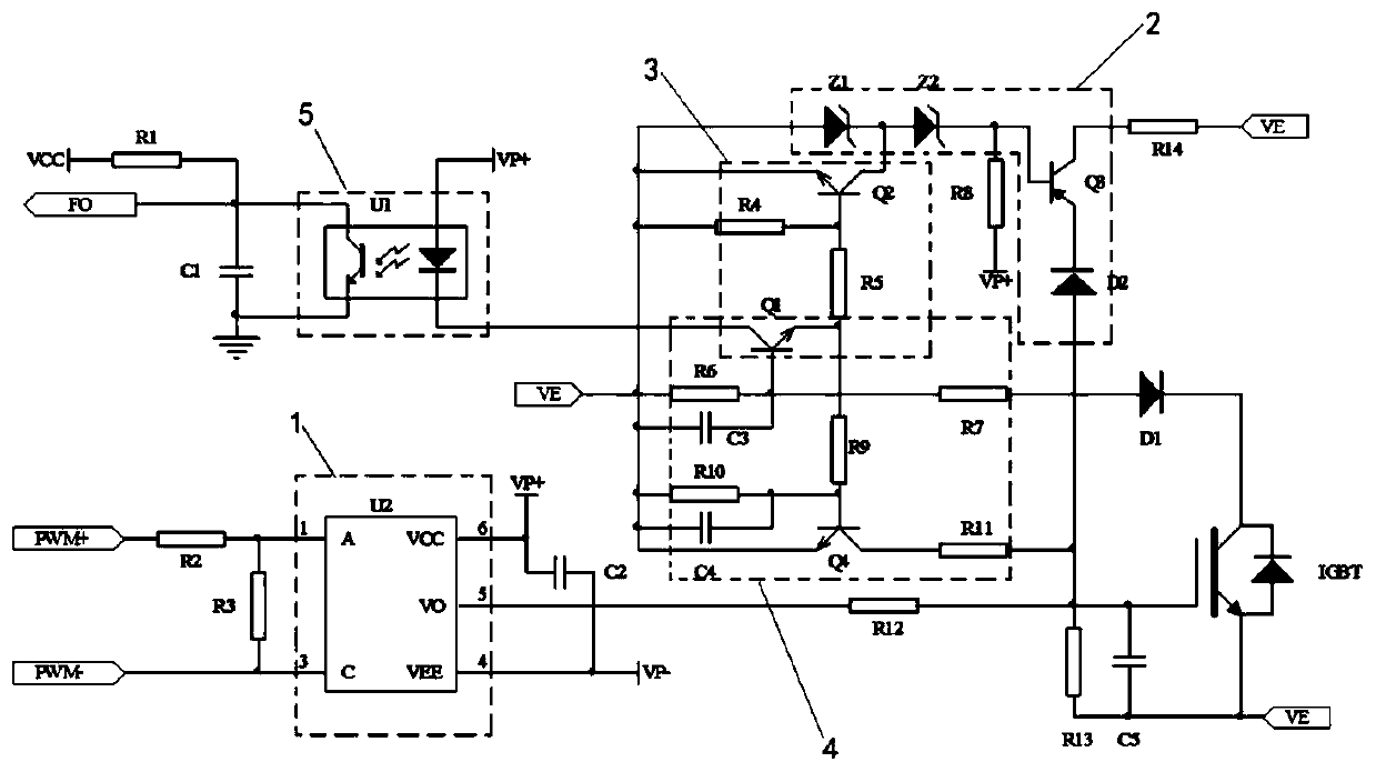
[0020] The inverter module drive and protection circuit provided by the invention is mainly composed of a common drive optocoupler and a common isolation optocoupler, three common N-type triodes, one common P-type triode, two 7.5V Zener diodes, two A fast recovery diode and resistors, capacitors. The inverter module is an IGBT.
[0021] The inverter module is an IGBT, and the output terminal of the drive optocoupler U2 is electrically connected to the gate of the inverter module IGBT through the twelfth resistor R12. When the inverter module IGBT passes a large current, the voltage passes through the inverter module IGBT gate The fifth capacitor C5 between the inverter module and the emitter charges the gate of the inverter module IGBT, so that the gate voltage of the inverter module IGBT rises, an...
PUM
 Abstract
Description
Claims
Application Information
 - R&D
- Intellectual Property
- Life Sciences
- Materials
- Tech Scout
- Unparalleled Data Quality
- Higher Quality Content
- 60% Fewer Hallucinations
Browse by: Latest US Patents, China's latest patents, Technical Efficacy Thesaurus, Application Domain, Technology Topic, Popular Technical Reports.
© 2025 PatSnap. All rights reserved.Legal|Privacy policy|Modern Slavery Act Transparency Statement|Sitemap|About US| Contact US: help@patsnap.com


