GPS scheduling monitoring terminal and use method

A monitoring terminal and GPS positioning technology, applied in the field of GPS dispatch monitoring terminal, can solve the problems of single structure function and poor use effect of GPS dispatch monitoring terminal, so as to improve the transmission efficiency and quality, improve the use efficiency, and achieve a high degree of intelligence. Effect

Inactive Publication Date: 2020-01-31
怀化市联翰信息科技有限公司
5 Cites 0 Cited by

AI-Extracted Technical Summary

Problems solved by technology

[0003] The existing GPS dispatching and monitoring terminal has a single structur...

Method used

In the present invention, sensing signal amplifying unit comprises first operational amplifier 18 and second operational amplifier 19, described first operational amplifier 18 anode input terminals connect diode A1b negative pole, described first operational amplifier 18 negative pole input terminals One end of the resistor B2a, one end of the resistor A1a and one end of the capacitor 20 are respectively connected, the other end of the resistor B2a is connected to the anode of the diode A1b, the two ends of the diode A1b are signal receiving ends, the other end of the resistor A1a and the other end of the capacitor 20 are respectively connected to the first The output terminal of the operational amplifier 18, the resistor C3a is connected between the output terminal of the first o...

Abstract

The invention discloses a GPS scheduling monitoring terminal and a use method. The terminal comprises a terminal body. The terminal body is installed in a vehicle. The front end surface of the terminal body is provided with a monitoring display screen. A plurality of alarm indicating lamps are arranged below the monitoring display screen. One side of the terminal body is provided with a data transmission interface. A control circuit board is installed in the terminal body. The control circuit board is provided with a control unit, a sensing signal amplification unit, a Beidou/GPS positioning unit, a vehicle power supply management unit, a scheduling matching unit, a scheduling server, a storage module and a communication module. The terminal is simple in working principle, is high in intelligent degree, can achieve the real-time remote monitoring and scheduling of a vehicle, and effectively improves the use efficiency of the vehicle.

Application Domain

Technology Topic

Image

  • GPS scheduling monitoring terminal and use method
  • GPS scheduling monitoring terminal and use method
  • GPS scheduling monitoring terminal and use method

Examples

  • Experimental program(1)

Example Embodiment

[0021] The technical solutions in the embodiments of the present invention will be clearly and completely described below in conjunction with the accompanying drawings in the embodiments of the present invention. Obviously, the described embodiments are only a part of the embodiments of the present invention, rather than all the embodiments. Based on the embodiments of the present invention, all other embodiments obtained by those of ordinary skill in the art without creative work shall fall within the protection scope of the present invention.
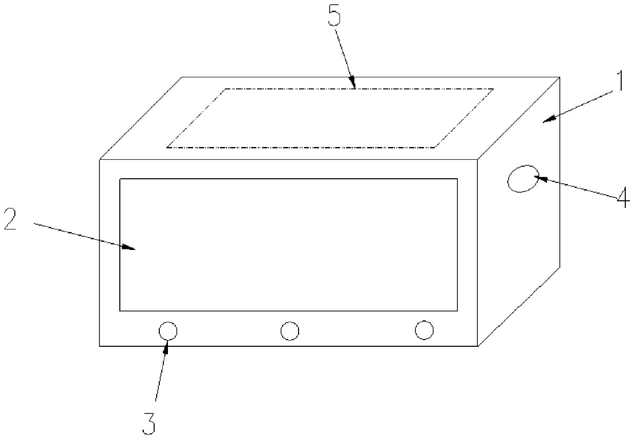
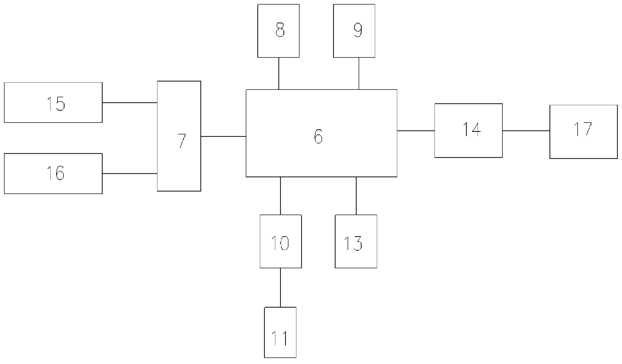
[0022] See Figure 1-3 , The present invention provides a technical solution: a GPS dispatch monitoring terminal, including a terminal body 1, the terminal body 1 is installed in a vehicle, the front end of the terminal body 1 is installed with a monitoring display screen 2, the monitoring display screen 2. A plurality of alarm indicator lights 3 are arranged below the terminal body 1, a data transmission interface 4 is arranged on one side of the terminal body 1, a control circuit board 5 is installed inside the terminal body 1, and a control unit 6 is installed on the control circuit board 5. Sensor signal amplification unit 7, Beidou/GPS positioning unit 8, vehicle power management unit 9, dispatch matching unit 10, dispatch server 11, storage module 12, alarm module 13, and communication module 14. The sensor signal amplification unit 7 inputs The terminals are respectively connected to the vehicle CCD image sensor 15 and the vehicle speed sensor 16, the output terminal of the sensing signal amplifying unit 7 is connected to the control unit 6, and the control unit 6 is respectively connected to the Beidou/GPS positioning unit 8, the vehicle power management unit 9, and dispatch matching Unit 10, alarm module 13, the dispatch matching unit 10 is connected to the dispatch server 11, the control unit 6 is connected to the background dispatch monitoring center 17 through the communication module 14, the communication module adopts the TD-LTE communication network; wherein, the sensor signal The amplifying unit is used to amplify the collected sensor signals, the Beidou/GPS positioning unit is used to monitor the vehicle position in real time, the vehicle power management unit is used to detect the power of the vehicle, and the dispatch matching unit is used to dispatch And match idle vehicles.
[0023] In the present invention, the Beidou/GPS positioning unit 8 includes a low-power Beidou GPS positioning chip and an antenna; the Beidou/GPS positioning unit receives satellite signals through the antenna for positioning, and uses the Beidou GPS dual-mode mode for positioning by default. When it is too weak to obtain satellite signals, it will automatically switch to single mode for positioning, or you can set the single mode to obtain satellite signals. Beidou/GPS positioning unit 8 has a dual-system multi-frequency performance SOC chip, which can support two frequency points BDB1 and GPS L1. It has the characteristics of high integration, low power consumption, and small size. The module has high sensitivity and can work under weak signal conditions. It provides excellent acquisition and tracking sensitivity, maintains the continuity and reliability of receiver positioning, and supports single-system independent positioning and multi-system joint positioning.
[0024] In the present invention, the sensing signal amplifying unit includes a first operational amplifier 18 and a second operational amplifier 19. The positive input of the first operational amplifier 18 is connected to the negative electrode of the diode A1b, and the negative input of the first operational amplifier 18 is respectively connected to a resistor. One end of B2a, one end of resistor A1a and one end of capacitor 20. The other end of resistor B2a is connected to the anode of diode A1b. Both ends of said diode A1b are signal receiving ends. The other end of resistor A1a and the other end of capacitor 20 are respectively connected to first operational amplifier 18. A resistor C3a is connected between the output terminal of the first operational amplifier 18 and the negative input terminal of the second operational amplifier 19, the positive input terminal of the second operational amplifier 19 is grounded, and the negative input terminal of the second operational amplifier 19 is connected to the A resistor D4a is connected between the output terminals, the output terminal of the second operational amplifier 19 is connected to the anode of the diode B2b, and the cathode of the diode B2b is the signal output terminal. The sensing signal amplifying unit adopted in the present invention adopts two operational amplifiers, which can amplify the signal step by step, thereby decomposing the work load, thereby improving the transmission efficiency and quality of the sensing signal, and further improving the scheduling efficiency.
[0025] Working principle: The use method of the present invention includes the following steps:
[0026] A. The vehicle CCD image sensor and the vehicle speed sensor respectively collect the image of the person in the vehicle and the vehicle speed signal, and the collected sensor signal is amplified by the sensor signal amplification unit and then transmitted to the control unit;
[0027] B. If the vehicle needs to be dispatched, first collect the vehicle status through sensors. If it is collected that there is no one in the vehicle and the vehicle is not running, then the Beidou/GPS positioning unit is used for vehicle positioning, and the collected position information is sent to the control unit;
[0028] C. At the same time, the control unit collects vehicle power supply information through the vehicle power management unit;
[0029] D. The dispatch server sends out vehicle usage requirements, and the dispatch matching unit automatically matches the number of idle vehicles and vehicle locations according to the vehicle usage requirements;
[0030] E. If the matched vehicle is scheduled to be used, the scheduling will be carried out, and if it is scheduled to be used, the search and matching will continue.
[0031] In summary, the present invention has simple working principle and high degree of intelligence, can realize real-time remote monitoring and scheduling of vehicles, can automatically match and schedule idle vehicles, and effectively improve the use efficiency of vehicles.
[0032] Although the embodiments of the present invention have been shown and described, those of ordinary skill in the art can understand that various changes, modifications, and substitutions can be made to these embodiments without departing from the principle and spirit of the present invention. And variations, the scope of the present invention is defined by the appended claims and their equivalents.

PUM

no PUM

Description & Claims & Application Information

We can also present the details of the Description, Claims and Application information to help users get a comprehensive understanding of the technical details of the patent, such as background art, summary of invention, brief description of drawings, description of embodiments, and other original content. On the other hand, users can also determine the specific scope of protection of the technology through the list of claims; as well as understand the changes in the life cycle of the technology with the presentation of the patent timeline. Login to view more.

Similar technology patents

Anti-failure pneumatic window opener

ActiveCN109914958ASimple working principleThe structure is easy to disassemblePower-operated mechanismWing openersPistonAir spring
Owner:郑州洪华建筑科技有限公司

Classification and recommendation of technical efficacy words

  • High degree of intelligence
  • Simple working principle

Safety rod driving system of liquid heavy metal cooling reactor

Owner:HEFEI INSTITUTES OF PHYSICAL SCIENCE - CHINESE ACAD OF SCI
Why Eureka
Try Eureka