
Implementation method of power LED pulse light source

A technology of pulsed light source and implementation method, applied in the field of LED light source, can solve the problems of increasing the design complexity of the pulsed light source, affecting the design reusability, increasing the use cost, etc., to achieve the effect of increasing portability, satisfying timely response, and convenient adjustment

Pending Publication Date: 2020-02-04
JIANGXI SCI & TECH NORMAL UNIV
View PDF0 Cites 0 Cited by
  • Summary
  • Abstract
  • Description
  • Claims
  • Application Information

AI Technical Summary

Problems solved by technology

Not only is the device bulky, which is not conducive to its application in portable aspects, but also increases the cost of use to a certain extent
[0005] The non-modular design form not only increases the complexity of the pulse light source design, but also seriously affects the reusability of the design

Method used


Image

  • Implementation method of power LED pulse light source
  • Implementation method of power LED pulse light source
  • Implementation method of power LED pulse light source

Examples


Embodiment 1

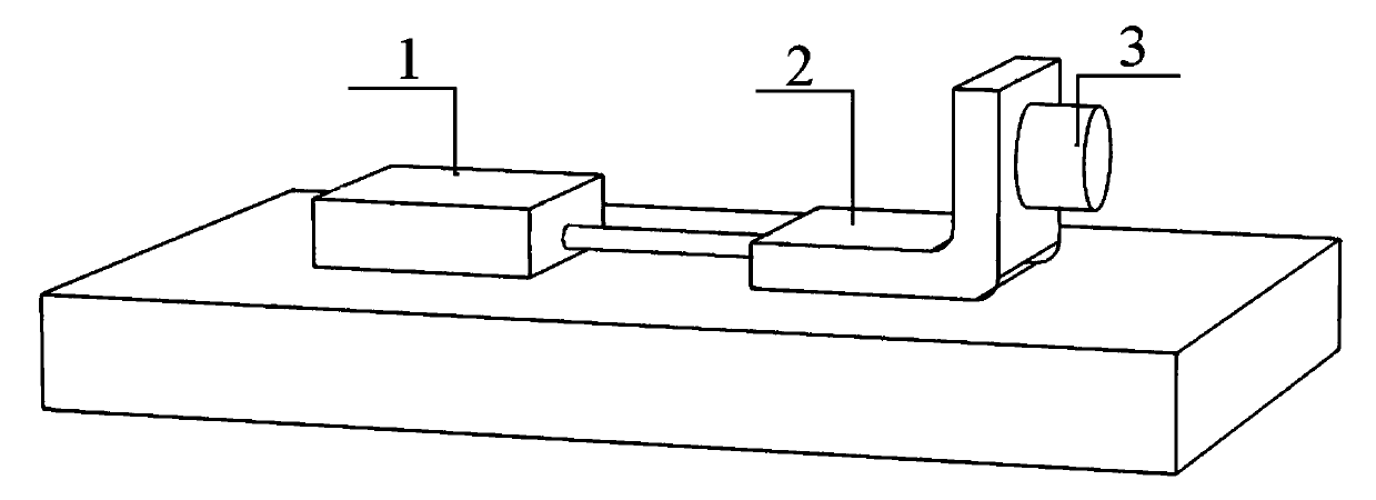
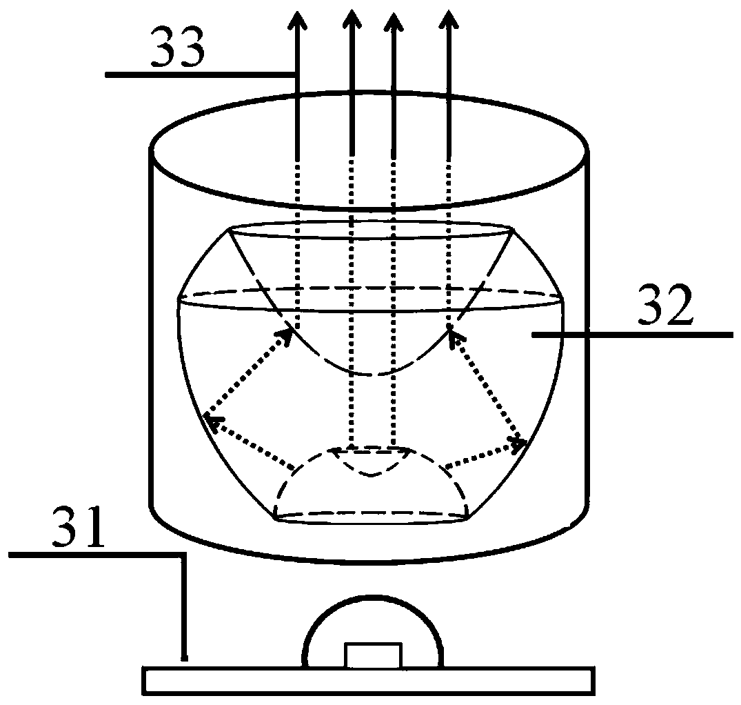
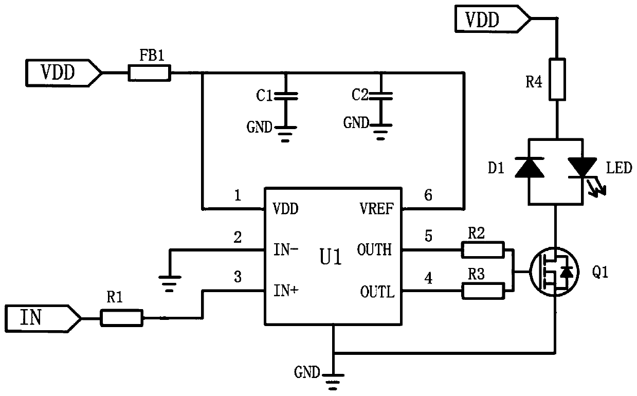
[0030] Embodiment 1, see figure 1 , a method for realizing a power-type LED pulse light source, including a pulse signal generating module 1, a drive circuit module 2, and an LED pulse light source module 3; wherein: the pulse signal generating module 1 is mainly composed of an FPGA chip, a crystal oscillator, a JTAG download interface and related configurations According to the requirements of the required pulse signal, the program is written in VHDL language, and the specific pulse signal is output directly through I / O; the driving circuit module 2 selects the appropriate The field effect tube driver U1 is used to drive the corresponding high-speed field effect tube, so that the circuit can achieve nanosecond response to achieve stable and continuous pulse output; the LED pulse light source module 3 is composed of a power type LED light source and a collimating lens. Through secondary light distribution, the LED pulse light source outputs parallel collimated beams.

Embodiment 2

[0031] Example 2, see Figure 4 , there is an embodiment to realize an optical pulse signal with a repetition frequency of 10 kHz and a pulse width of 50 ns. That is, through program writing and burning, the pulse signal generation module outputs the required electrical pulse signal a at the I / O, and the pulse signal a is input into the drive circuit module through electrical connection, and the FET responds quickly under the control of the pulse signal, and the control The LED pulse light source module works in a pulse mode to generate a predetermined optical pulse signal b.

[0032] The invention relates to a method for realizing a power type LED pulse light source, in which, except a pulse signal generation module which needs a 5V DC voltage for power supply, other parts can be powered by a DC adjustable power supply.

[0033] The invention relates to a method for realizing a power type LED pulse light source, wherein the power type LED light source is used as the pulse li...


PUM


Abstract

The invention discloses an implementation method of a power LED pulse light source. Currently, common pulse light sources are mostly LD pulse light sources, and the complexity and high price limit thedevelopment of the pulse light sources; and the application range of other types of pulse light sources is greatly limited by a low frequency, a high duty ratio, limited pulse signal regulation and other factors. The implementation method of the power LED pulse light source is mainly divided into three modules, namely a pulse signal generation module, a driving circuit module and an LED pulse light source module, wherein the signal generation module based on an FPGA outputs a pulse signal meeting a predetermined requirement through a program, then the pulse signal is input into a driving circuit, the on / off state of an MOS transistor is controlled, and then the LED pulse light source is driven to work through the driving circuit. Due to modular design, the power LED pulse light source with adjustable pulse width and pulse frequency, wide wavelength coverage, a simple structure, a small size and a low cost is provided, and the development of the LED pulse light source is powerfully promoted.

Description

technical field [0001] The invention relates to an LED light source, in particular to a method for realizing a power type LED pulse light source. Background technique [0002] As the fourth-generation electric light source, LED light source is known as "green lighting source" and has remarkable characteristics such as high efficiency, energy saving, environmental protection, and easy maintenance. However, LEDs will generate a lot of heat due to continuous high-intensity current, which will seriously affect their optical properties and service life; at the same time, the preparation of power LED light sources is still severely restricted in terms of heat dissipation, so the application of power LEDs in the field of special lighting applications are more common. Therefore, when the power LED is driven by pulse, not only will it not seriously affect its optical properties and service life, but it can use the characteristics of narrow pulses to obtain higher intensity lighting ...

Claims


Application Information

Patent Timeline
Patent Type & Authority Applications(China)
IPC IPC(8): H05B45/32F21K9/69F21Y115/10
CPCF21K9/69F21Y2115/10
Inventor 熊志华赵德志陈聪牛云飞
Owner JIANGXI SCI & TECH NORMAL UNIV
Learn More