Cooler and thermosyphon

A thermosyphon, cooler technology, applied in indirect heat exchangers, electrochemical generators, lighting and heating equipment, etc., can solve the problems of unstable liquid refrigerant supply, unstable cooling, etc.

Active Publication Date: 2020-02-04
DENSO CORP
View PDF6 Cites 3 Cited by
  • Summary
  • Abstract
  • Description
  • Claims
  • Application Information

AI Technical Summary

Problems solved by technology

[0013] Therefore, the supply of the liquid-phase refrigerant from the refrigerant supply flow path 2a to the evaporation

Method used


Image

  • Cooler and thermosyphon
  • Cooler and thermosyphon
  • Cooler and thermosyphon

Examples


no. 1 approach

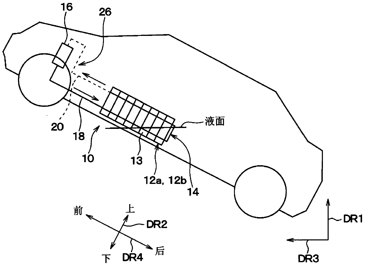
[0076] figure 1 The battery cooling unit 10 of the present embodiment shown is installed in electric vehicles such as electric vehicles and hybrid vehicles. Furthermore, in the present embodiment, the battery cooling unit 10 cools the secondary batteries 12a and 12b mounted on the electric vehicle. That is, the object to be cooled by the battery cooling unit 10 is the secondary batteries 12a and 12b.

[0077] In an electric vehicle equipped with a battery cooling unit 10 (hereinafter, simply referred to as a "vehicle"), the electric power stored in a power storage device (in other words, a battery pack) including the secondary batteries 12a and 12b as constituent components is converted to Circuits and the like are supplied to the electric motor, whereby the vehicle travels. The secondary batteries 12a and 12b generate heat by themselves when outputting electric power to the electric motor via the inverter.

[0078] Moreover, if the temperature of the secondary batteries 1...

no. 2 approach

[0224] In this second embodiment, refer to Figure 15 ~ Figure 1 8. An example in which the battery cooling unit 10 is configured by connecting two coolers 14 of the above-mentioned first embodiment in series will be described.

[0225] The battery cooling structure for cooling the secondary batteries 12a and 12b using the cooler 14 is different between the present embodiment and the first embodiment described above. Therefore, below, the battery cooling structure in the battery cooling unit 10 will be described, and the description of other structures will be omitted.

[0226] The battery cooling unit 10 of the present embodiment includes two coolers 14 and two pairs of secondary batteries 12a and 12b as a battery cooling structure.

[0227] The two coolers 14 are configured in the same manner as the coolers 14 of the first embodiment described above. Two coolers 14 are arranged along the traveling direction of the vehicle. Hereinafter, for convenience of description, the ...

no. 3 approach

[0241] In the above-mentioned second embodiment, the example in which the two coolers 14 are arranged in the traveling direction of the vehicle has been described, but instead, refer to Figure 18A , Figure 18B , Figure 19A , Figure 19B The present third embodiment in which three coolers 14 are arranged in a line in the traveling direction of the vehicle will be described. Among the two coolers of the three coolers 14 , the cooler located on the front side in the traveling direction corresponds to the first cooler, and the cooler located on the front side in the traveling direction corresponds to the second cooler. The inlet 14a of the cooler 14 corresponding to the first cooler corresponds to the first refrigerant inlet, and the inlet 14a of the cooler 14 corresponding to the second cooler corresponds to the second refrigerant inlet.

[0242] The battery cooling structure for cooling the secondary batteries 12a and 12b using the cooler 14 is different between the presen...


PUM


Abstract

This cooler, together with a condenser (16) that condenses a gas-phase coolant and discharges a liquid-phase coolant, constitutes a thermosyphon that causes a coolant to circulate. The cooler comprises: first channel forming parts (60a, 60b, 60c) that form a supply channel (70) through which the liquid-phase coolant from the condenser flows; second channel forming parts (60a, 43, 60b, 44) that form evaporation channels (61a, 61b) that have coolant inlets (64a, 64b) that communicate with the supply channel, that are formed to extend upward from the coolant inlets, and that cause the liquid-phase coolant to evaporate through heat exchange between cooling targets (12a, 12b) and the liquid-phase coolant that flows in from the supply channel via the coolant inlets, thereby causing the gas-phasecoolant to be generated; and third channel forming parts (60a, 60b, 45) that form a discharge channel (71) through which the gas-phase coolant from the evaporation channels flows toward the condenser. The coolant inlets are located below a vertical center part of the supply channel.

Description

[0001] Cross-references to related applications [0002] This application is based on Japanese Patent Application No. 2017-118870 filed on June 16, 2017, the contents of which are incorporated herein by reference. technical field [0003] The present disclosure relates to a cooler and a thermosyphon (Japanese: サーモサイフォン). Background technique [0004] Conventionally, among thermosyphons, there is a thermosyphon that includes a cooler that cools the battery by evaporating the liquid-phase refrigerant through heat exchange between the liquid-phase refrigerant and the battery, and that uses the gas-phase gas from the cooler to cool the battery. The condenser condenses the refrigerant, and constitutes a refrigerant circuit that circulates the refrigerant between the cooler and the condenser (for example, refer to Patent Document 1). [0005] prior art literature [0006] patent documents [0007] Patent Document 1: Specification of Japanese Patent No. 59429943 [0008] Referr...

Claims


Application Information

Patent Timeline
IPC IPC(8): F28D15/02F28D15/06
CPCF28D15/02F28D15/06F28D15/025F28D15/0266F28D2015/0216H01M10/625F28D2021/0028F28D2021/008Y02E60/10H01M10/6563H01M10/6567H01M10/6569H01M10/6555H01M10/653H01M10/6557H01M10/633H01M10/6552F28D15/0275
Inventor 大见康光义则毅三浦功嗣竹内雅之
Owner DENSO CORP
Why Eureka
Try Eureka