
Conversion of co-fed methane and hydrocarbon feedstocks into higher value hydrocarbons

a technology of hydrocarbon feedstock and hydrocarbon feedstock, which is applied in the direction of hydrocarbon oil treatment products, thermal non-catalytic cracking, organic chemistry, etc., can solve the problems of not being able to prefer steam, and achieve the reduction or elimination of the need for hydrogen diluent, the reduction of the need for additional hydrogen, and the increase of the ratio of methane to the separated vapor phase

Active Publication Date: 2008-12-04
EXXONMOBIL CHEM PAT INC
View PDF56 Cites 72 Cited by
  • Summary
  • Abstract
  • Description
  • Claims
  • Application Information

AI Technical Summary

Benefits of technology

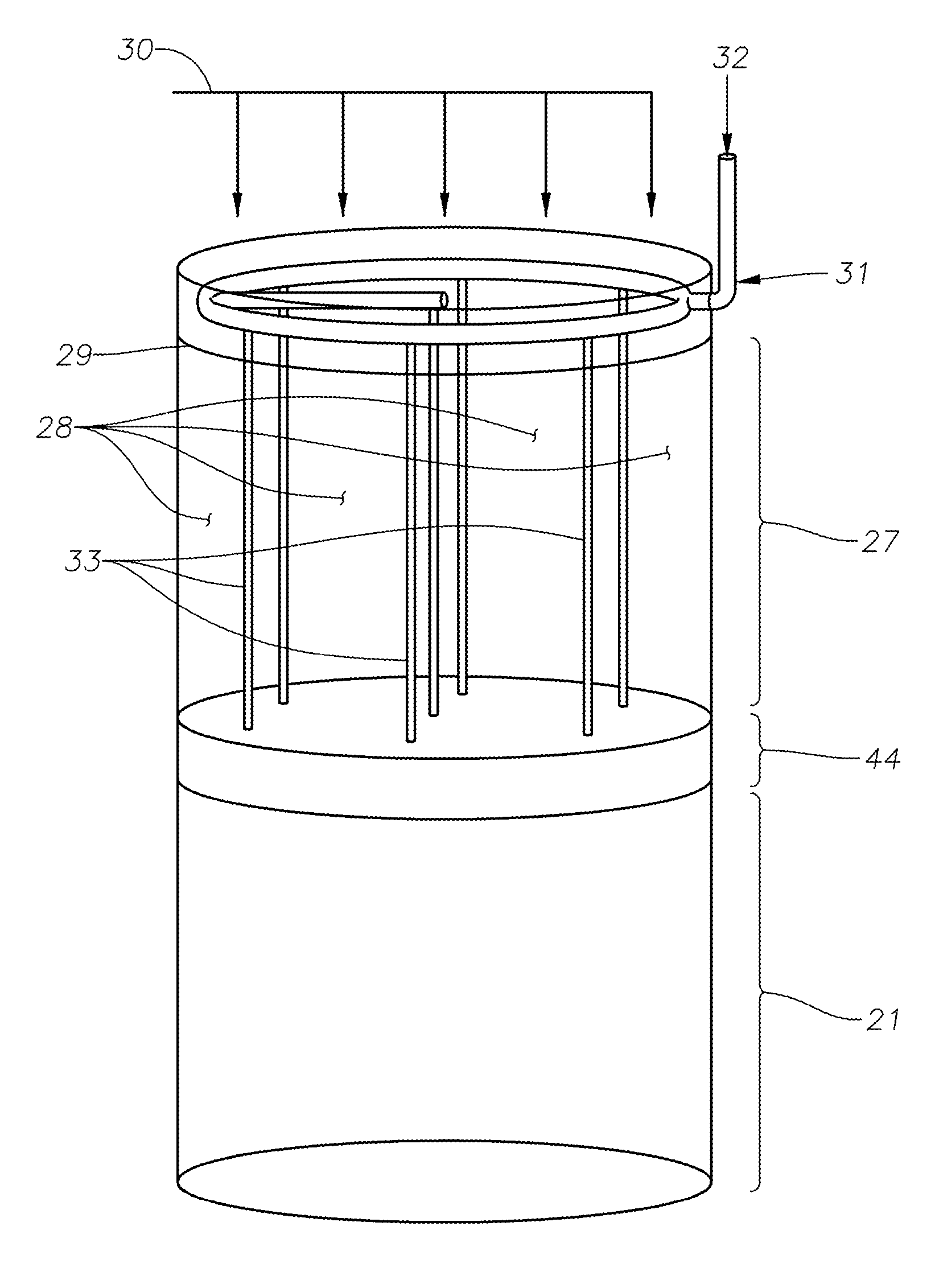
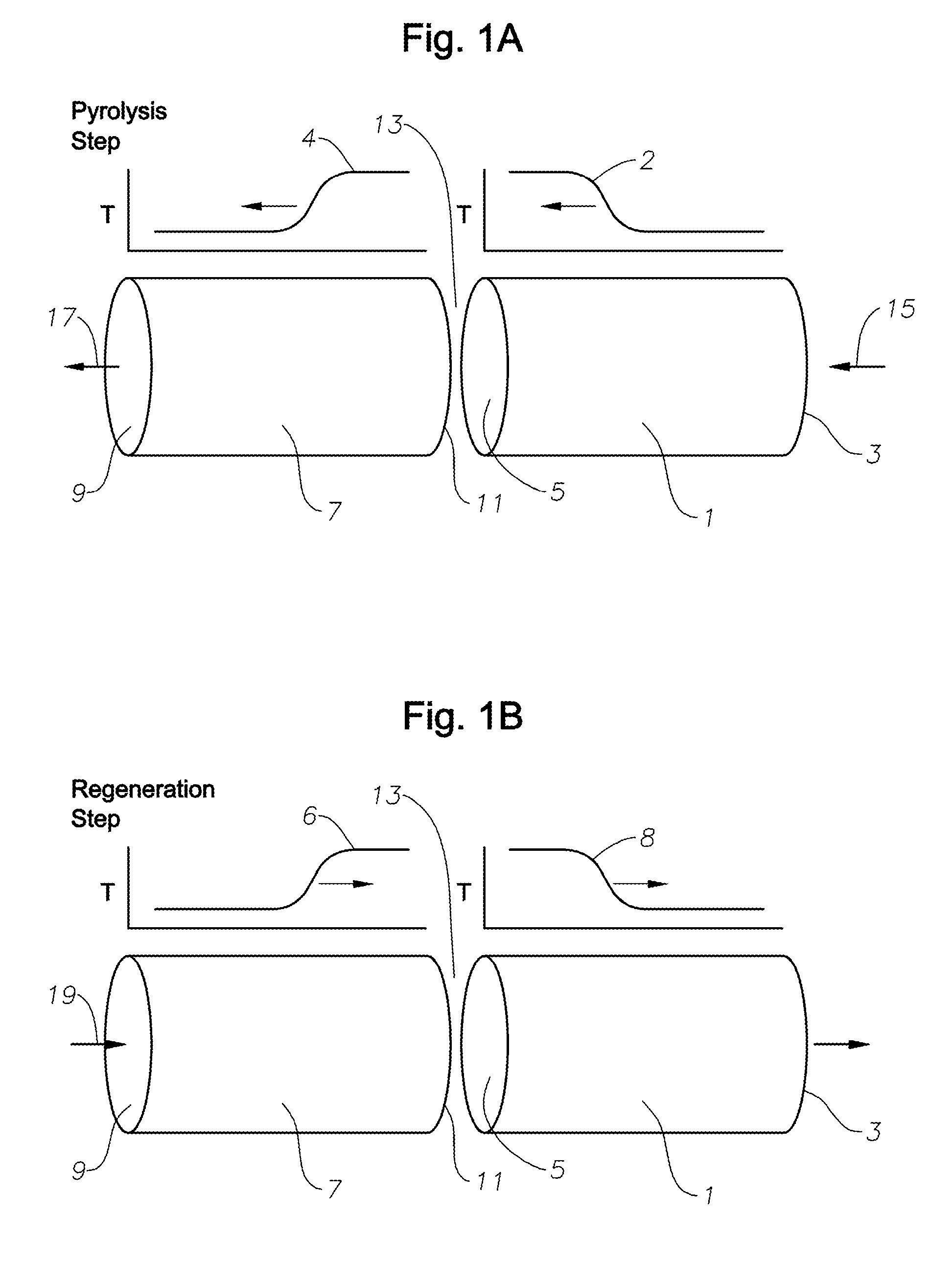
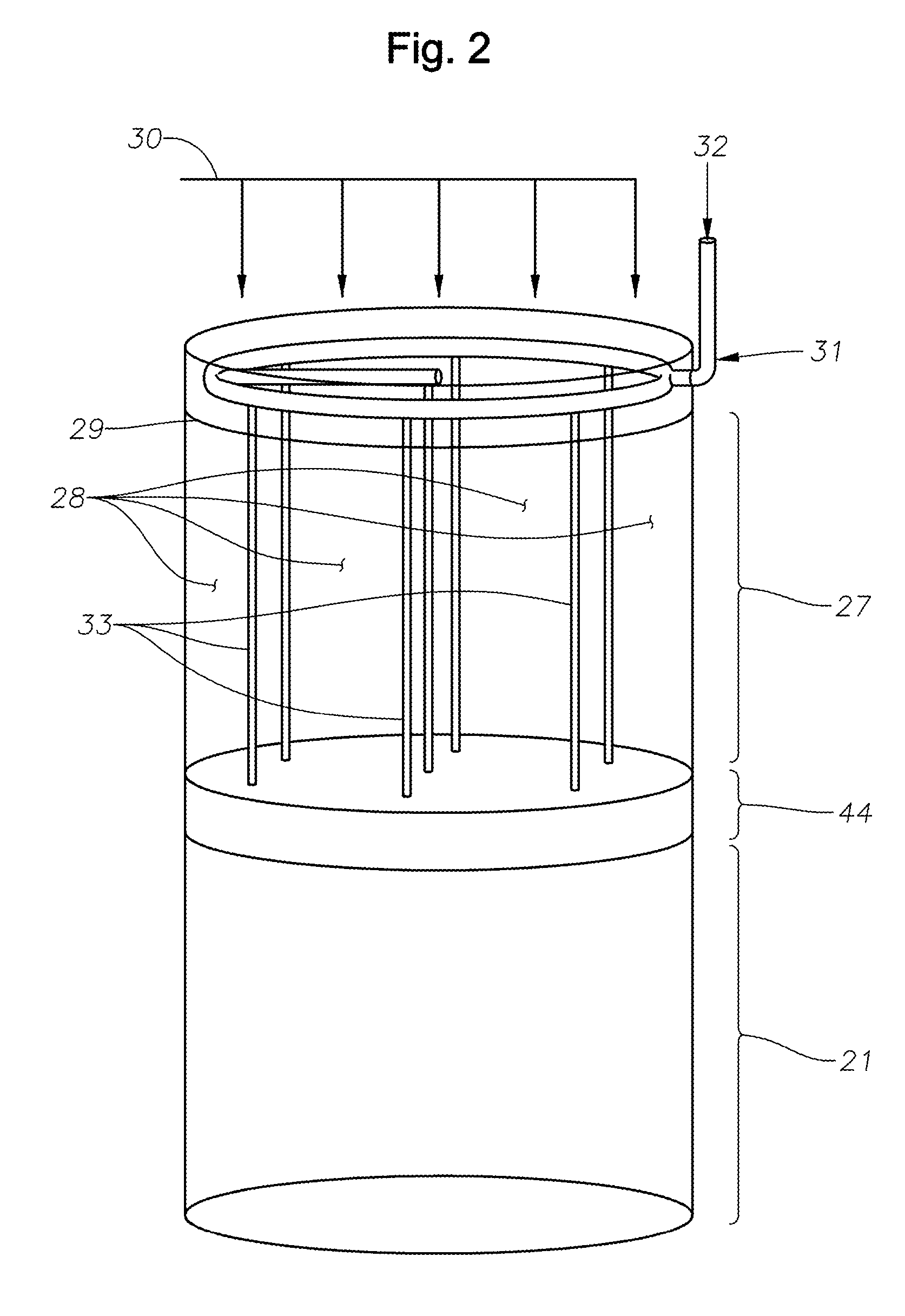
[0010]In another embodiment, the invention includes the step of feeding a diluent or stripping agent, such as hydrogen, to the pyrolysis reactor system in conjunction with the separated vapor phase and methane feed, for cracking the mixed vapor phase and methane in the presence of the diluent or stripping agent, within the regenerative pyrolysis reactor system. Hydrogen may typically be a preferred diluent or stripping agent. Steam may be used as a diluent or stripping agent for some alternative processes. However, steam may not be preferred in many processes, in that, unlike steam cracking, at pyrolysis reactor temperatures, such as above 1200° C., steam can react with hydrocarbon to form carbon monoxide and hydrogen. However, depending upon the amount of methane present, the need for hydrogen diluent may be reduced or eliminated. The reaction of cracking the methane to acetylene will yield free hydrogen which can serve as a stripping agent or diluent. Therefore, the need for additional hydrogen may be reduced as the ratio of methane to separated vapor phase is increased.

Problems solved by technology

However, steam may not be preferred in many processes, in that, unlike steam cracking, at pyrolysis reactor temperatures, such as above 1200° C., steam can react with hydrocarbon to form carbon monoxide and hydrogen.

Method used


Image

  • Conversion of co-fed methane and hydrocarbon feedstocks into higher value hydrocarbons
  • Conversion of co-fed methane and hydrocarbon feedstocks into higher value hydrocarbons
  • Conversion of co-fed methane and hydrocarbon feedstocks into higher value hydrocarbons

Examples


Embodiment Construction

[0017]The terms “convert” and “converting” are defined broadly herein to include any molecular decomposition, cracking, breaking apart, conversion, and / or reformation of organic molecules in the hydrocarbon feed, by means of at least pyrolysis heat, and may optionally include supplementation by one or more of catalysis, hydrogenation, diluents, and / or stripping agents.

[0018]As used herein, the expression “essentially free of nonvolatiles” means that concentration of nonvolatiles in the vapor phase is reduced to an extremely low level. Those skilled in the art know that it is difficult to obtain a complete separation of nonvolatiles from a hydrocarbon feedstock such as crude oil. As a result, the vapor phase may contain a trace amount of nonvolatiles. Therefore, in the context of the present invention, while it is the objective that the vapor phase contains no nonvolatiles, it is recognized that the vapor phase may contain an acceptable trace amount of nonvolatiles, e.g., typically a...


PUM

PropertyMeasurementUnit
temperatureaaaaaaaaaa
weight percentaaaaaaaaaa
boiling pointaaaaaaaaaa

Abstract

In one aspect, the inventive process comprises a process for pyrolyzing a hydrocarbon feedstock containing nonvolatiles in a regenerative pyrolysis reactor system. The process comprises: (a) heating the nonvolatile-containing hydrocarbon feedstock upstream of a regenerative pyrolysis reactor system to a temperature sufficient to form a vapor phase that is essentially free of nonvolatiles and a liquid phase containing the nonvolatiles; (b) separating said vapor phase from said liquid phase; (c) feeding the separated vapor phase and methane to the pyrolysis reactor system; and (d) converting the methane and separated vapor phase in said pyrolysis reactor system to form a pyrolysis product. In another aspect, the invention includes a separation process that feeds multiple pyrolysis reactors.

Description

RELATIONSHIP TO OTHER APPLICATIONS[0001]This application claims benefit of U.S. provisional application Ser. No. 60 / 933,011, filed Jun. 4, 2007, and claims benefit of U.S. provisional application Ser. No. 60 / 933,044, filed Jun. 4, 2007, the entirety of which are incorporated herein by reference.FIELD OF THE INVENTION[0002]This invention pertains to conversion of hydrocarbons using regenerative pyrolysis reactors. The invention relates to a process for cracking hydrocarbons present in hydrocarbon feedstocks containing nonvolatiles, in a regenerative pyrolysis reactor. The nonvolatiles are removed from the feedstocks before the hydrocarbons undergo thermal pyrolysis. More particularly the invention relates to a process and apparatus for improving the quality of nonvolatile-containing feedstocks to a regenerative pyrolysis reactor system or a plurality of such pyrolysis reactor systems.BACKGROUND OF THE INVENTION[0003]Conventional steam crackers are known as an effective tool for crack...

Claims


Application Information

Patent Timeline
Patent Type & Authority Applications(United States)
IPC IPC(8): C07C15/02C07C2/00B01J19/00
CPCC10G9/26C10G69/06C10G2300/807C10G2300/802C10G2400/20C10G2300/301Y02P30/40
Inventor KEUSENKOTHEN, PAUL F.HERSHKOWITZ, FRANK
Owner EXXONMOBIL CHEM PAT INC
Learn More