
Multifunctional die box

A mold box, multi-functional technology, applied in the direction of drawing dies, etc., can solve the problems of lubricating powder accumulation in corners, agglomeration, difficult to use effectively, etc., to improve the effect of agitation and the effect of sufficient agitation

Pending Publication Date: 2020-02-07
GUIZHOU AEROSPACE NANHAI SCI & TECH
View PDF0 Cites 1 Cited by
  • Summary
  • Abstract
  • Description
  • Claims
  • Application Information

AI Technical Summary

Problems solved by technology

[0003] In the prior art, a stirring device is installed on the mold box body. The stirring device is provided with a stirring rod inserted into the powder chamber to stir the lubricating powder to ensure the smearing effect of the lubricating powder. In order to facilitate processing, the mold box is usually a square structure. Among them, it is difficult to touch the bottom corner of the mold box when doing circular motion, and some lubricating powder accumulates in the corner for a long time, or even agglomerates, which is difficult to use effectively

Method used


Image

  • Multifunctional die box
  • Multifunctional die box
  • Multifunctional die box

Examples


Embodiment 1

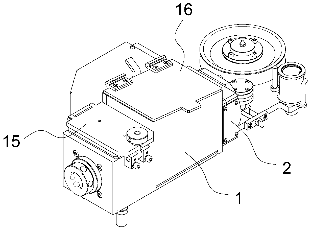
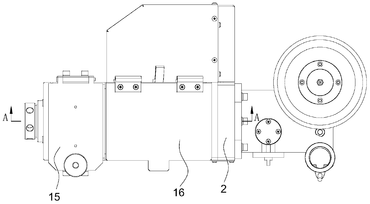
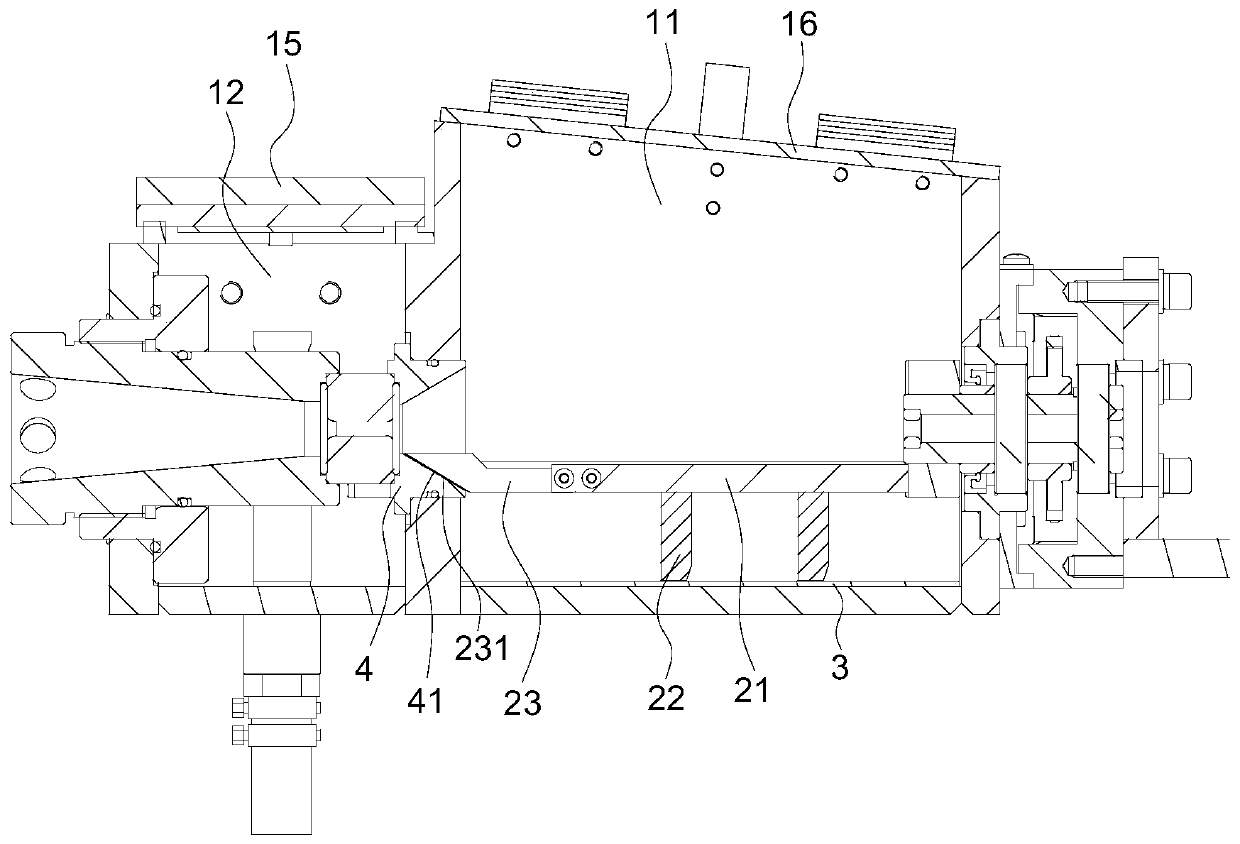
[0041] Such as Figure 1 to Figure 6As shown, a multifunctional mold box includes a box body 1 and an agitating mechanism 2. The box body 1 is provided with a powder chamber 11, and the bottom of the powder chamber 11 is provided with a groove bottom plate 3. The groove bottom plate 3 is a semicircular tube, and the opening of the groove bottom plate 3 Put it upwards to hold the lubricating powder. The box body 1 is provided with a back mold cover 4, and the back mold cover 4 is provided with a taper hole 41 to guide the wire to pass through the mold box during drawing. The stirring mechanism 2 and the box body 1 Fixed connection, stirring mechanism 2 comprises stirring rod 21, and stirring rod 21 rotates around metal wire, and the axis of rotation of stirring rod 21 coincides with the center line of tank bottom plate 3, and stirring rod 21 is provided with several first scrapers 22 at intervals, the first The bottom surface of the scraper 22 is matched with the inner circular...

Embodiment 2

[0047] Such as Figure 7 , Figure 8 As shown, on the basis of the structure of Embodiment 1, the first scraper 22 is a rectangular plate, and the first scraper 22 is provided with a plurality of through grooves 221, and when the lubricant powder is stirred, the lubricant powder can pass through the grooves 221 , change the position, improve the effect of agitation, which is beneficial to evenly suspend the agitating lubricating powder in the powder cavity, and evenly deposit on the metal wire passing by at high speed. The central planes of two adjacent first scrapers 22 intersect to form an angle. When stirring The lubricating powder can be squeezed to both sides to make the agitation more sufficient and further improve the agitation effect. The center plane of the first scraper 22 passes through the centerline of the bottom plate 3 of the groove, and one end of the first scraper 22 is fixed on the stirring rod 21 , the other end of the first scraper 22 is provided with an a...

Embodiment 3

[0049] Such as Figure 9 , Figure 10 As shown, on the basis of the structure of Embodiment 1, the middle part of the upper end of the first scraper 22 is fixed on the stirring rod 21, and intersects with the stirring rod 21 to form an included angle. When stirring, the lubricating powder can be squeezed to both sides, so that Agitation is more sufficient to improve the effect of agitation. The first scraper 22 is provided with a number of through holes 223. When agitating the lubricating powder, the lubricating powder can pass through the holes 223, change the position, and further improve the effect of agitation, which is conducive to agitation and lubrication. The powder is evenly suspended in the powder chamber, and evenly deposited on the high-speed passing metal wire. The first scraper 22 is provided with a curved surface 224. The curved surface 224 is matched with the inner circular surface of the groove bottom plate 3. The axial projection is an arc to ensure that the...


PUM


Abstract

The invention provides a multifunctional die box. A box body and a stirring mechanism are included. The box body is provided with a powder cavity. A groove bottom plate is arranged at the bottom of the powder cavity and is a half circular pipe. An opening of the groove bottom plate is arranged upwards. The box body is provided with a die supporting sleeve, and the die supporting sleeve is providedwith a conical hole. The stirring mechanism is fixedly connected with the box body and comprises a stirring rod. The rotation axis of the stirring rod coincides with the center line of the groove bottom plate. A plurality of first scrapers are arranged on the stirring rod at intervals. The bottom faces of the first scrapers are in clearance fit with the inner circle face of the groove bottom plate. A second scraper is arranged at the front end of the stirring rod and provided with a scraping face, and the scraping face and the hole wall of the conical hole are in clearance fit. The multifunctional die box is provided, through the arrangement of the semicircular groove bottom plate and the stirring mechanism which are matched, lubricating powder at the bottom of the powder cavity can be sufficiently stirred, the lubricating powder utilization efficiency is improved, the lubricating powder usage amount is reduced, and cost is saved.

Description

technical field [0001] The invention belongs to the field of material drawing equipment, and in particular relates to a mold box for a wire drawing machine. Background technique [0002] When the wire drawing machine draws the metal wire, it is often equipped with a mold box, which is filled with lubricating powder. When the metal wire passes through the mold box, the lubricating powder can be applied to reduce the friction between the metal wire and the production equipment, and ensure that the metal wire is smooth during the drawing process. The medium can run at high speed to ensure production efficiency and stable product quality. [0003] In the prior art, a stirring device is installed on the mold box body. The stirring device is provided with a stirring rod inserted into the powder cavity to stir the lubricating powder to ensure the smearing effect of the lubricating powder. The mold box is usually square in order to facilitate processing. Among them, it is difficult...

Claims


Application Information

Patent Timeline
Patent Type & Authority Applications(China)
IPC IPC(8): B21C3/14B21C9/00
CPCB21C3/14B21C9/00
Inventor 李华孙明功
Owner GUIZHOU AEROSPACE NANHAI SCI & TECH
Learn More