Auxiliary device for laser cutter workbench

A laser cutting machine and auxiliary device technology, applied in auxiliary devices, welding/cutting auxiliary equipment, laser welding equipment, etc., can solve the problems of reduced cutting quality, cutting errors, and easy shaking of materials, so as to increase stability and avoid shaking , the effect of improving accuracy

Active Publication Date: 2020-02-07
JINAN BODOR LASER CO LTD
View PDF8 Cites 0 Cited by
  • Summary
  • Abstract
  • Description
  • Claims
  • Application Information

AI Technical Summary

Problems solved by technology

The worktable does not have a material clamping device, which causes the material to shake easily during the cutting process, resulting in cutting errors and reduced cutting quality. An auxiliary workbench device is urgently needed to clamp the material to ensure the stability of the material feeding

Method used


Image

  • Auxiliary device for laser cutter workbench
  • Auxiliary device for laser cutter workbench
  • Auxiliary device for laser cutter workbench

Examples


Embodiment 1

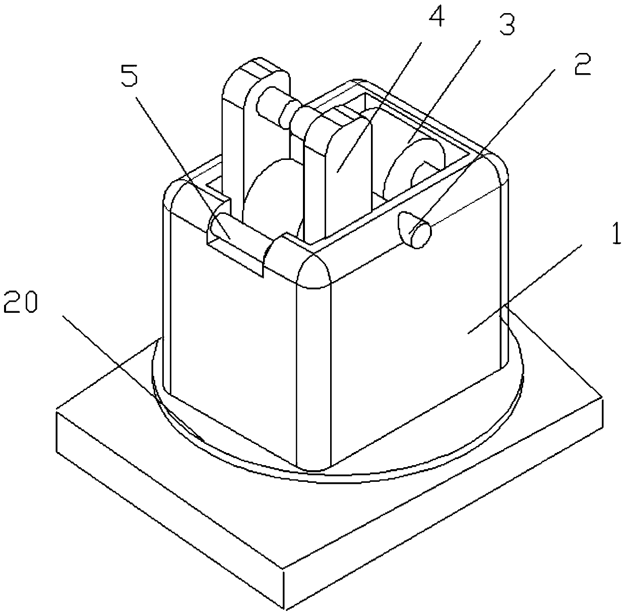
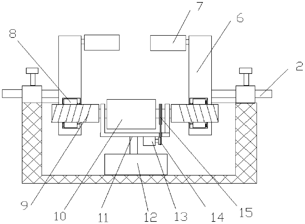
[0025] see Figure 1-4 , an auxiliary device for a laser cutting machine table, including a housing 1 , a first transmission device 4 and a second transmission device 3 . The bottom of the casing 1 is fixedly arranged on the upper surface of the rotating seat 20, and the rotating seat 20 can be rotated, so that the casing 1 can rotate, which facilitates the adjustment of the horizontal cutting angle of the material. The proximal side wall of the casing 1 is rotatably provided with a supporting roller 5, which has a supporting effect on the material, avoids contact between the material and the casing 1, and makes feeding of the material more convenient. The first transmission device 4 includes a first rotating roller 10, a threaded roller 9 and a vertical rod 6, the first rotating roller 10 is rotatably arranged at the inner proximal end of the housing 1, and the inner proximal end of the housing 1 is equipped with a first cylinder 12, The first cylinder 12 is connected with a...

Embodiment 2

[0030] see Figure 5 , On the basis of Embodiment 1, the outer side of the drive sleeve 8 is fixedly provided with a multi-prism sleeve 22 , and the inner and outer sides of the vertical rod 6 are provided with grooves corresponding to the multi-prism sleeve 22 . Under the action of the spring 18, the transmission sleeve 8 and the rotating sleeve 19 slide outwards, the polygonal column sleeve 22 is stuck inside the groove, and the threaded roller 9 rotates to drive the transmission sleeve 8 and the vertical rod 6 to move. When the inner side of the vertical bar 6 clamps the material and is resisted, the transmission sleeve 8 is stressed and the polygonal column sleeve 22 is disengaged from the groove.


PUM


Abstract

The invention relates to the technical field of cutters and particularly discloses an auxiliary device for a laser cutter workbench. The device comprises a shell and a first transmission device, the first transmission device comprises a first rotation roller and vertical rods, threaded rollers are coaxially and fixedly connected to the two sides of the first rotation roller, and a driven wheel iscoaxially connected to the first rotation roller and one threaded roller. A motor is fixedly installed in the shell, and a drive wheel is coaxially connected to the motor. The threaded rollers are nested in the bottoms of the vertical rods, transmission sleeves are nested on the bottoms of the vertical rods, and inner threads are arranged in the transmission sleeves. The outer sides of the transmission sleeves are provided with connectors, rotation sleeves are rotatably connected to the inner sides of the transmission sleeves, and the rotation sleeves are elastically connected to the inner side walls of the vertical rods through springs. Rotation wheels are rotatably arranged on the inner sides of the tops of the vertical rods, and a second transmission device is fixedly arranged on the portion, in the shell, of the far side of the first transmission device. The auxiliary device for the laser cutter workbench has the advantages of being simple in structure, convenient to operate, firmto fix, stable to convey, high in applicability, capable of improving the cutting quality and convenient to operate and popularize.

Description

technical field [0001] The invention relates to the technical field of cutting machines, in particular to an auxiliary device for a workbench of a laser cutting machine. Background technique [0002] Due to the fast cutting speed, laser cutting is widely used in the cutting of thick metal sheets. However, because the thickness of thick metal sheets is generally 14-20mm and the area is large, the thick metal sheets are very heavy. The traditional thick metal sheet feeding All materials are loaded by hand, and they have to be carried by multiple people. Due to the heavy weight of thick metal plates, it is difficult to carry, and the efficiency of manual handling is low. A simpler way is to use some hoisting equipment to lift the material. The lifted material is easy to shake, resulting in reduced cutting quality, which is not easy to popularize and implement. [0003] Chinese patent (notification number: CN 205147833 U, announcement date: 2016.04.13) discloses a cutting machi...

Claims


Application Information

Patent Timeline
IPC IPC(8): B23K26/70B23K37/04B23K26/08B23K26/38
CPCB23K26/0861B23K26/38B23K37/0435B23K26/702
Inventor 杨绪广于飞路世强韩小鹏
Owner JINAN BODOR LASER CO LTD
Why Eureka
Try Eureka