
Novel carbon fiber composite material telescope antenna panel structure

A composite material and antenna panel technology, which is applied to antennas, electrical components, layered products, etc., can solve the problems that the thermal stability of the panel structure cannot meet the requirements of antenna accuracy and affect the observation efficiency of high-precision telescopes. The effect of observing efficiency

Inactive Publication Date: 2020-02-07
NANJING UNIV OF AERONAUTICS & ASTRONAUTICS
View PDF3 Cites 0 Cited by
  • Summary
  • Abstract
  • Description
  • Claims
  • Application Information

AI Technical Summary

Problems solved by technology

However, from the results of simulation and low-temperature tests, the thermal stability of the panel structure with aluminum honeycomb as the core material cannot meet the accuracy requirements of the antenna, and the high coefficient of thermal expansion (CTE) in the normal direction of the honeycomb will still cause the surface shape to change in temperature. There are slight changes when changing, but this is enough to affect the observation efficiency of high-precision telescopes

Method used


Image

  • Novel carbon fiber composite material telescope antenna panel structure
  • Novel carbon fiber composite material telescope antenna panel structure
  • Novel carbon fiber composite material telescope antenna panel structure

Examples


Embodiment Construction

[0014] In order to make the object, technical solution and effect of the present invention clearer and clearer, the following examples are given to further describe the present invention in detail. It should be pointed out that the specific implementations described here are only used to explain the present invention, not to limit the present invention.

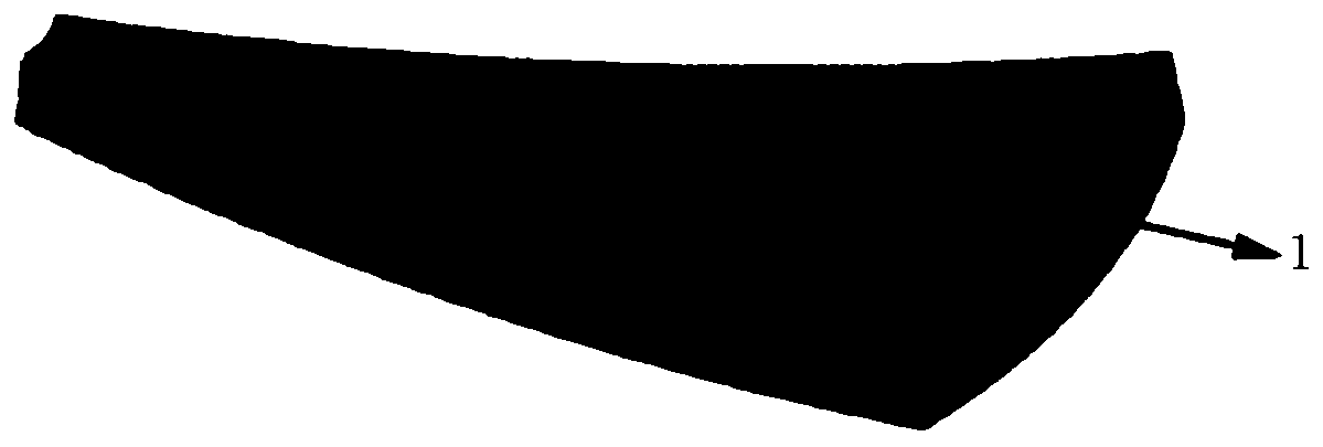
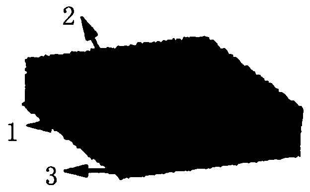
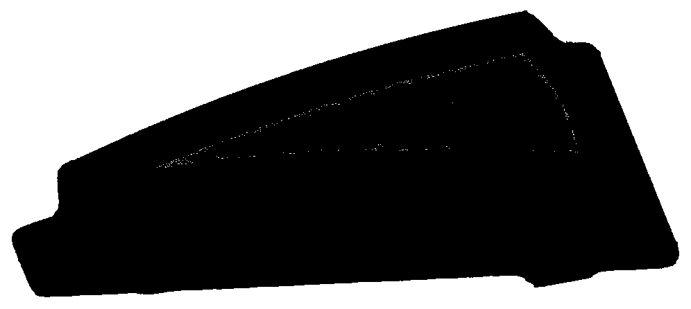
[0015] Such as figure 1 As shown, it is a schematic diagram of a novel carbon fiber composite telescope antenna panel structure of the present invention, including a panel body, which is composed of a core material 1 and a skin wrapped on the outer surface of the core material 1, and the core material 1 is a carbon fiber tube array structure, the skin is a carbon fiber laminate, and the carbon fiber laminate is connected to the outer surface of the carbon fiber sandwich structure through resin curing and bonding. Such as figure 2 The carbon fiber tube array structure shown is a vertical dense arrangement, and the arrangeme...


PUM

PropertyMeasurementUnit
surface smoothnessaaaaaaaaaa

Abstract

The invention discloses a novel carbon fiber composite material panel structure, and belongs to the technical field of heat preservation. The panel structure comprises a panel main body, wherein the panel main body is composed of a core material, and a skin wrapping the outer surface of the core material, the core material is of a carbon fiber sandwich structure, the skin is a carbon fiber laminated plate, the carbon fiber laminated plate is connected with the outer surface of the carbon fiber sandwich structure through resin curing and cementation, and the carbon fiber sandwich structure is of a carbon fiber tube array structure. In the panel structure, a traditional aluminum honeycomb sandwich structure is replaced by the carbon fiber tube array structure, the influence of a temperaturechange on the surface shape precision of an antenna panel is reduced, and the observation efficiency of a high-precision telescope is ensured.

Description

technical field [0001] The invention relates to the technical field of heat preservation, in particular to a novel carbon fiber composite telescope antenna panel structure. Background technique [0002] The panel constitutes the main reflector of the antenna. The main reflector is an important part of the telescope system to collect faint radiation from celestial bodies. The accuracy of its surface shape will directly affect the light collection efficiency of the telescope, so it has extremely high precision requirements. In the extreme site environment that is favorable for astronomical observation, carbon fiber reinforced composite materials are a more reasonable and advanced material choice. It has small thermal deformation, high specific strength, and large specific modulus. Therefore, in the scheme of the main reflector of the antenna, the size of a single panel can be large, and the total number of panels is small, which is conducive to rapid installation and adjustmen...

Claims


Application Information

Patent Timeline
Patent Type & Authority Applications(China)
IPC IPC(8): B32B9/00B32B9/04B32B3/20B32B3/22B32B7/12B32B33/00H01Q15/16H01Q19/19
CPCB32B3/18B32B3/20B32B5/08B32B5/26B32B7/12B32B33/00B32B2250/20B32B2262/106B32B2307/308H01Q15/16H01Q19/19
Inventor 吴楠钱元蔡登安周光明
Owner NANJING UNIV OF AERONAUTICS & ASTRONAUTICS
Learn More