Tendon transmission system with composite tendon sheath and tendon sheath restraining elements

A transmission system and tendon sheath technology, applied in the field of tendon transmission system, can solve the problems of large internal cutting force, low structural reliability, and other joints, and achieve the effect of reducing friction and simple and reliable structure

Pending Publication Date: 2020-02-07
NEUROCEAN TECH INC
View PDF0 Cites 3 Cited by
  • Summary
  • Abstract
  • Description
  • Claims
  • Application Information

AI Technical Summary

Problems solved by technology

However, most of the current tendon drive schemes still have some inherent problems that have not been well resolved.
[0004] The first problem is that there is a lot of friction between the tendon and the tendon sheath, both of which are prone to wear; and because the tendon and the tendon sheath can bend, when a large tension is applied to make the tendon very tight, the inner wall of the tendon to the tendon sheath bends Causes a large internal cutting force, which can easily cut the tendon sheath
[0005] The second problem is that when the tendon sheath spans one or more cascaded joints, a certain device is required at the joint to constrain the position, orientation and deformation range of the tendon sheath
The current solutions include two types: one is to install gears or pulleys at the joints as relay transmission parts, but this solution causes too many moving parts at the joints, lowers the structural reliability, and takes up a lot of space; the other One is to install a rigid semi-enclosed guide rail or chute structure at the joint so that the tendon sheath

Method used


Image

  • Tendon transmission system with composite tendon sheath and tendon sheath restraining elements
  • Tendon transmission system with composite tendon sheath and tendon sheath restraining elements
  • Tendon transmission system with composite tendon sheath and tendon sheath restraining elements

Examples


Embodiment Construction

[0062] The technical solutions in the embodiments of the present invention will be clearly and completely described below with reference to the accompanying drawings in the embodiments of the present invention. Obviously, the described embodiments are only a part of the embodiments of the present invention, but not all of the embodiments. Based on the embodiments of the present invention, all other embodiments obtained by those of ordinary skill in the art without creative efforts shall fall within the protection scope of the present invention.

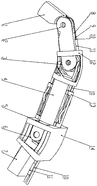
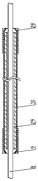
[0063] see attached figure 1 and attached Figure 8 , the embodiment of the present invention discloses a tendon transmission system with a composite tendon sheath and a tendon sheath restraining element, the system includes: tendon 8, a composite tendon sheath 10, a tendon sheath fixing element 11, and a tendon sheath restraining element.

[0064] The tendon sheath restraining elements include: type I tendon sheath restraint element...


PUM


Abstract

The invention discloses a tendon transmission system with a composite tendon sheath and tendon sheath restraining elements. The transmission system references tendons, tendon sheathes and ligament tissues of human hands and provides a composite tendon sheath structure composed of an inner tendon sheath and an outer tendon sheath, so that the friction between the tendon and the tendon sheath can beeffectively reduced, and the side cutting force of the tendon is prevented from damaging the tendon sheath; an I-shaped tendon sheath restraining element, an II-shaped tendon sheath restraining element, an III-shaped tendon sheath restraining element and an IV-shaped tendon sheath restraining element are proposed, so that position and the range of motion of the tendon sheath can be flexibly constrained and cannot be removed, the movement of each joint spanned by the tendon sheath can be decoupled from each other, and certain anti-pressure and impact-resistant protection is provided for the tendon sheath. The transmission system has the advantages that the transmission system is simple and reliable in structure, high in service life, and easy to maintain, and has certain flexibility and the like, and is particularly suitable for being applied to bionic dexterous hands, bionic mechanical feet or other robotic mechanisms requiring tendon transmission.

Description

technical field [0001] The invention belongs to the field of transmission devices for dexterous hands or bionic mechanical feet, in particular to a tendon transmission system with composite tendon sheaths and tendon sheath restraining elements. Background technique [0002] A bionic dexterous hand refers to a manipulator whose index, degrees of freedom, shape and function are close to that of a human hand. It can manipulate objects flexibly and finely. Performance prosthesis; bionic mechanical foot refers to the mechanical foot of a biped or quadruped robot, which is mainly used to make the robot walk, run, jump and climb flexibly and flexibly on various ground and terrain. The bionic dexterous hand and the bionic mechanical foot are the key components and devices of the bionic robot or the humanoid robot. Their common features are small size and large number of joints. They all need to transmit greater force in a small space through the transmission system, and often The n...

Claims


Application Information

Patent Timeline
IPC IPC(8): B62D57/032B25J17/02B25J15/08B25J19/00
CPCB62D57/032B25J17/02B25J17/0241B25J17/0208B25J15/08B25J19/0062B25J19/0075B25J9/104B25J15/0009
Inventor 任化龙李文强
Owner NEUROCEAN TECH INC
Why Eureka
Try Eureka