Gas suspension device in vapor deposition furnace

A technology of gas and suspension devices in the furnace, which is applied in the direction of gaseous chemical plating, metal material coating technology, coating, etc., can solve the problems that easily affect the normal suspension and rotation of graphite disks, affect the uniformity of gas flow, and front pore corrosion Large and other problems, to achieve the effect of improving uniformity and quality, good suspension effect, and smooth rotation

Pending Publication Date: 2020-02-07
深圳市志橙半导体材料有限公司
View PDF0 Cites 0 Cited by
  • Summary
  • Abstract
  • Description
  • Claims
  • Application Information

AI Technical Summary

Problems solved by technology

[0003] The graphite disk rotating device in the prior art usually includes a graphite disk and a base. The main air passage in the base is directly connected with two inclined air holes for generating rotating gas to push the graphite disk to suspend and rotate. One of the inclined air holes is in the front and the other is in the rear. The resistance flowing through the front pores is smaller than that of the rear pores, so more gas flows through the front pores, and the front pores are also corroded by the process gas, resulting in the increase of the front pores and affecting the uniformity of the gas flow, which is easy to affect the graphite. Normal levitation and rotation of the disc, causing the device to fail

Method used


Image

  • Gas suspension device in vapor deposition furnace
  • Gas suspension device in vapor deposition furnace
  • Gas suspension device in vapor deposition furnace

Examples


Embodiment Construction

[0019] The present invention will be further described below in conjunction with the description of the drawings and specific embodiments.

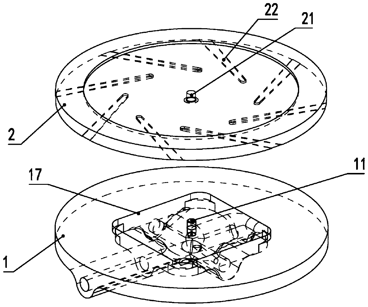
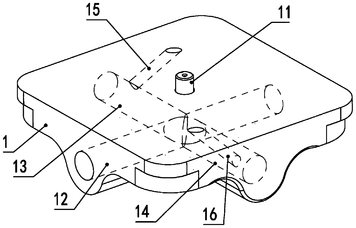
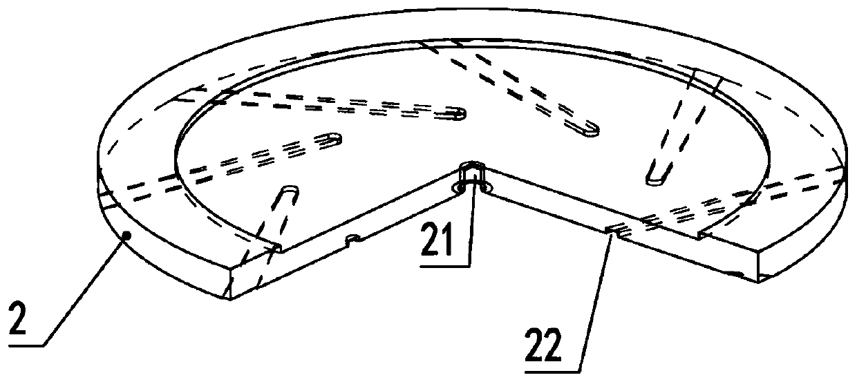
[0020] Such as Figure 1 to Figure 4 As shown, a gas suspension device in a vapor deposition furnace includes a graphite disk 2 and a base 1 arranged in parallel and rotatably matched, and the base 1 is provided with a main air inlet 12, a first gas distribution hole 13, and a second gas distribution hole 14. The first inclined air outlet hole 15 and the second inclined air outlet hole 16. The first air distribution hole 13 and the second air distribution hole 14 are respectively located on both sides of the main air inlet hole 12. The first air distribution hole 13, The second air distribution hole 14 is connected with the main air inlet hole 12 respectively at the same point, the first air distribution hole 13 is connected with the first inclined air outlet hole 15, and the second air distribution hole 14 is connected with the second ai...


PUM


Abstract

The invention provides a gas suspension device in a vapor deposition furnace. The gas suspension device comprises a graphite disc and a base which are arranged in parallel and are rotationally matched. A main air inlet hole, a first air distribution hole, a second air distribution hole, a first inclined air outlet hole and a second inclined air outlet hole are formed in the base. The first air distribution hole and the second air distribution hole are located in the two sides of the main air inlet hole and are intersected and communicate with the main air inlet hole at the same point. The gassuspension device has the beneficial effects that the first air distribution hole and the second air distribution hole are separated at the same position of the main air inlet hole, then rotating gases are generated through the first inclined air outlet hole and the second inclined air outlet hole, the graphite disc is pushed to suspend and rotate, it is ensured that the gas flowing resistance isconsistent, it is ensured that the flow of the two inclined gases is the same, the suspension effect is good, rotating is smooth, the uniformity and quality of films can be obviously improved, and theservice cycle of the device is effectively prolonged.

Description

technical field [0001] The invention relates to a vapor deposition furnace, in particular to a gas suspension device in a vapor deposition furnace. Background technique [0002] The fundamentals of vapor deposition involve reaction chemistry, thermodynamics, kinetics, transfer mechanisms, film growth phenomena, and reaction engineering. Mainly use vapor such as metal vapor, volatile metal halide, hydride or metal organic compound as raw material, carry out gas phase thermal decomposition reaction, and the reaction of two or more simple substances or compounds, and then condense to form materials in various forms. In the chemical vapor deposition process, the uniformity of the deposited film is extremely important, and the uniformity of the film is mainly affected by the gas distribution in the furnace. The chemical vapor deposition process is an extremely complex chemical process. Whether the gas is evenly distributed will have a great impact on the deposition rate of the p...

Claims


Application Information

Patent Timeline
IPC IPC(8): C23C16/455
CPCC23C16/45502
Inventor 黄洪福蓝图袁永红雷宏涛
Owner 深圳市志橙半导体材料有限公司
Why Eureka
Try Eureka