
A mortar spraying device

A spraying device and mortar technology, applied in construction, building structure and other directions, can solve the problems of mortar splashing and reducing cleaning workload, and achieve the effect of preventing splashing, reducing cleaning workload and increasing stability.

Active Publication Date: 2020-12-01
徐州世威隆盛建设工程有限公司
View PDF7 Cites 0 Cited by
  • Summary
  • Abstract
  • Description
  • Claims
  • Application Information

AI Technical Summary

Problems solved by technology

[0007] The technical problem mainly solved by the present invention is to provide a mortar spraying device. This device reduces the waste of mortar and saves costs. At the same time, the device saves a lot of water resources in cleaning, reduces the cleaning workload, and saves a lot of working time. At the same time, the device solves the problem of The problem of mortar splashing is avoided to affect the working efficiency of the device

Method used


Image

  • A mortar spraying device
  • A mortar spraying device
  • A mortar spraying device

Examples


specific Embodiment approach 1

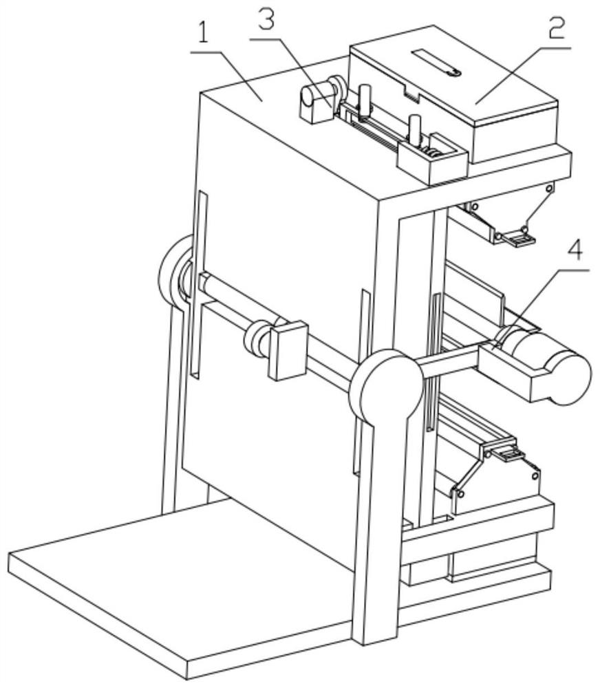
[0044] Combine below Figure 1-22Description of this embodiment, a mortar spraying device, including a device mounting frame 1, a mortar box 2, an impact mechanism 3 and a shooting mechanism 4, the shooting mechanism 4 is installed on the device mounting frame 1, each of the mortar box 2 There are two numbers, respectively installed at the two ends of the device mounting frame 1, and the positions are symmetrical, and there are two impact mechanisms 3, respectively installed at the upper and lower ends of the device mounting frame 1, and the positions are symmetrical.

specific Embodiment approach 2

[0046] Combine below Figure 1-22 Describe this embodiment, this embodiment will further explain the first embodiment, the device mounting frame 1 includes a fixed frame 1-1, an arc-shaped slider 1-2, a supporting side plate 1-3, a base 1-4, and an arc Shaped slider 1-2 is fixedly installed on the fixed frame 1-1, and arc-shaped slider 1-2 is movably installed on the support side plate 1-3. There are two support side plates 1-3, which are respectively fixed on On both sides of the base 1-4, the arc-shaped sliding piece 1-2 and the supporting side plate 1-3 complete the rotation of the device, the structure is simple and reasonable, and the cost of the device is reduced.

specific Embodiment approach 3

[0048] Combine below Figure 1-22 Describe this embodiment, this embodiment will further explain the second embodiment, the mortar box 2 includes a top cover 2-1, a cleaning assembly 2-2, a box body 2-3, a pull-out baffle 2-4, a movable Cover 2-5, the movable cover 2-5 is fixedly connected with the box body 2-3 by screws, the top cover 2-1 is movably installed on the box body 2-3, and the cleaning component 2-2 is movably installed on the top cover 2-1 On the set groove, there are two movable covers 2-5, the movable cover 2-5 is hinged with the box body 2-3, and the positions are symmetrical, and the pull-out baffle 2-4 is movably installed on the box body 2 On the through hole provided on -3, the box body 2-3 is fixedly installed on the fixed frame 1-1; the cleaning assembly 2-2 includes a cleaning frame 2-2-1, a cylinder 2-2-2, and a handle 2-2 -3, the handle 2-2-3 is hinged to the cylinder 2-2-2, the cylinder 2-2-2 is fixedly installed on the cleaning frame 2-2-1, and the ...


PUM


Abstract

The invention relates to a building spraying device, in particular to a mortar spraying device. The mortar spraying device comprises a device mounting rack, mortar boxes, impact mechanisms and an injection mechanism. By means of the mortar spraying device, waste to mortar is reduced, and cost is saved; meanwhile, the device saves a large number of water resources on clearing, the clearing work amount is reduced, and a large amount of work time is saved; and meanwhile, the problem of mortar splashing is solved by the device, and the work efficiency of the device is prevented from being influenced. The injection mechanism is mounted on the mounting rack of the device, the number of the mortar boxes is two, the mortar boxes are mounted at the two ends of the mounting rack of the device correspondingly and are symmetric in position, the number of the impact mechanisms is two, and the impact mechanisms are mounted at the upper end and the lower end of the mounting rack of the device correspondingly and are symmetric in position.

Description

technical field [0001] The invention relates to a construction spraying device, in particular to a mortar spraying device. Background technique [0002] The mortar spraying machine is used for plastering the building wall. The mortar spraying machine on the market has high requirements on the workability of the mortar, and it is easy to cause the blockage of the conveying pipeline. The mortar spraying machine needs to be cleaned with water after use. , wasting a large amount of water resources. In view of the above problems, the inventor found an invention in the authorized state: the spraying direction gradient type mortar spraying device. This invention uses the principle of centrifugal force to change the working principle of the mortar spraying machine on the market, thereby avoiding The problem of pipeline blockage is solved, and this invention also solves the problem of spraying direction, but this invention has many drawbacks. [0003] The shortcoming that this inven...

Claims


Application Information

Patent Timeline
Patent Type & Authority Patents(China)
IPC IPC(8): E04F21/08E04F21/12
CPCE04F21/08E04F21/12
Inventor 王辉
Owner 徐州世威隆盛建设工程有限公司
Learn More