Fan assembly of built-in generator

A technology for fan components and generators, applied in the directions of electric components, engine components, electrical components, etc., can solve the problems of increasing the power supply capacity of the engine, low output power efficiency, and large additional weight, etc., to improve the power supply capacity, convenient installation, and easy The effect of maintenance

Inactive Publication Date: 2020-02-07
中国航发贵阳发动机设计研究所
View PDF4 Cites 2 Cited by
  • Summary
  • Abstract
  • Description
  • Claims
  • Application Information

AI Technical Summary

Problems solved by technology

[0004] The purpose of the present invention is to overcome the problems of low output power efficiency and large additional weight of the existing mechanical transmission methods, and propose a fan assembly with a built-in generator, which extracts power from the low-pressure rotor and realizes the growth of the power supply capacity of the engine

Method used


Image

  • Fan assembly of built-in generator

Examples


Embodiment Construction

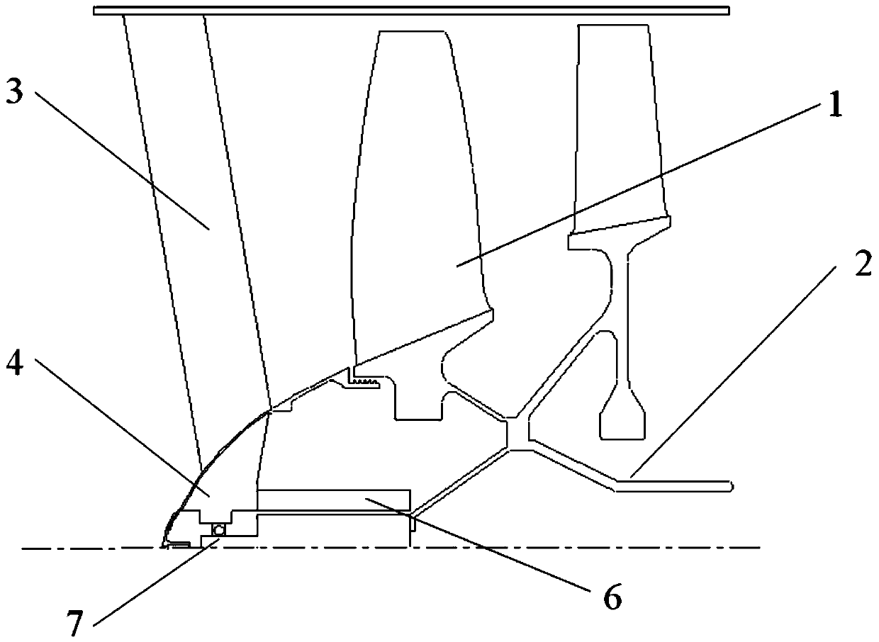
[0010] Taking the built-in electric excitation doubly salient generator as an example, the present invention proposes a fan assembly with a built-in generator in detail, as follows: figure 1 As shown, the dual-rotor turbofan engine fan built-in electrically-excited double-salient pole generator solution is used to install electrically-excited double-salient pole motors 4 and 5 in the cavity of the fan 1 and the intake cone 4 to extract low-voltage rotor power, wherein the motor The rotor 5 is installed on the fan shaft 2, and the motor stator is installed on the intake cone 4, and is fixed by the intake support plate. When the low-pressure rotor of the dual-rotor turbofan engine rotates, the motor rotor 4 is rotated, and the motor rotor 4 and the motor stator 5 cut the magnetic induction lines to generate electric energy. In order to realize the scheme of building electric excitation doubly salient generators 4 and 5 in the fan 1, it is necessary to carry out some adaptive imp...


PUM


Abstract

The invention belongs to the structural design scheme of aero-engines and relates to a fan assembly of a built-in generator. The fan assembly is composed of a fan rotor, a coupling shaft, an air inletsupport plate, an air inlet cone, a motor and a bearing, wherein the fan rotor is a self component of the generator and rotates at a high speed; the front end of the fan rotor is connected with the coupling shaft; a motor rotor is mounted on the coupling shaft; the fan rotor drives the motor rotor to rotate through the coupling shaft; the air inlet support plate is mounted on a fan casing; the fan casing is connected with a bearing casing; the fan casing and the bearing casing are self force transmitting components of the generator; the air inlet cone is mounted on the air inlet support plateand is static; a sealing structure is arranged at the connecting position of the air inlet cone and the rotor; and a motor stator a bearing for supporting the motor rotor are fixedly mounted on the air inlet cone. The fan assembly can improve the power supply capacity of the generator and reduces the weight of the generator; and the built-in motor is convenient to mount and easy to maintain.

Description

technical field [0001] The invention relates to an aeroengine fan assembly, in particular to a fan assembly with a built-in generator. Background technique [0002] With the increase of power-consuming accessories such as aircraft onboard radars, sensors, weapons, etc., the aircraft requires more and more power for the power supply of the engine. The power obtained by the output power of the "aircraft accessory case-generator" route is not enough to meet the power demand of the aircraft. In order to further increase the power supply capacity of the engine and meet the operational needs of the aircraft, a scheme of building a generator in the fan of the aeroengine for power extraction is proposed. [0003] Although the mechanical transmission power output method used on the high-voltage rotor is mature and widely used, it requires a complex and heavy transmission device. If the low-voltage rotor adopts the mechanical transmission method to output power, the weight burden on ...

Claims


Application Information

Patent Timeline
Patent Type & Authority Applications(China)
IPC IPC(8): F01D15/10F01D25/24F01D11/00F01D25/18H02K7/14
CPCF01D11/00F01D15/10F01D25/18F01D25/24H02K7/14
Inventor 刘鹏飞赵凯
Owner 中国航发贵阳发动机设计研究所
Why Eureka
Try Eureka