Magnetic fluid sealing rotary joint

A magnetic fluid seal and rotary joint technology, which is applied to engine seals, pipes/pipe joints/fittings, adjustable connections, etc., can solve problems such as large frictional resistance, short-lived seals, friction and wear, and avoid contact friction , Avoid adhesive wear and long service life

Pending Publication Date: 2020-02-07
GENERAL ENG RES INST CHINA ACAD OF ENG PHYSICS
View PDF0 Cites 5 Cited by
  • Summary
  • Abstract
  • Description
  • Claims
  • Application Information

AI Technical Summary

Problems solved by technology

[0003] At present, most of the rotary joints adopt the contact seal design, which generally has the problems of large frictional resistance, short service life and easy generation of seal wear particles, which will pollute the operating environment of the equipment.
The non-contact rotary joint is a high-end product among various types of rotary joints. It has the characteristics of high pressure and high speed. Its main seal adopts a non-contact gap seal, but it cannot achieve zero leakage. Some products use contact seals such as oil seals. The second seal can achieve zero leakage, but it also brings the problem of friction and wear. The life of the rotary joint is limited by the second contact seal

Method used


Image

  • Magnetic fluid sealing rotary joint
  • Magnetic fluid sealing rotary joint
  • Magnetic fluid sealing rotary joint

Examples


Embodiment Construction

[0032] The present invention will be further described below in conjunction with accompanying drawing:

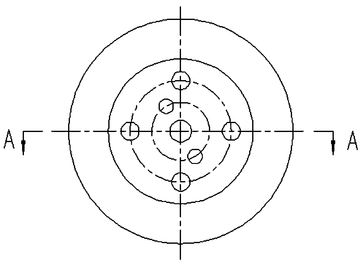
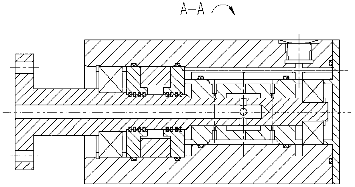
[0033] like Figure 1-3 shown;

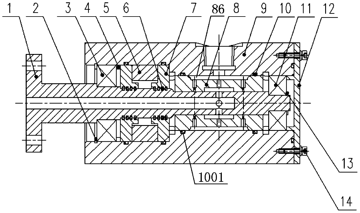
[0034] Ferrofluid sealed rotary unions, including:

[0035] A shaft 1; a first airway is formed in the shaft 1;

[0036] Floating ring 8; the floating ring 8 is formed into a ring; a second air passage is formed in the floating ring 8; at least two rows of throttle holes 81 are arranged on the radial direction of the floating ring 8, and one end of the throttle hole 81 is connected to the floating ring 8 and The gap between the shafts 1 communicates, and the other end of the throttle hole 81 communicates with the second air passage;

[0037] The pole shoe 7; the pole shoe 7 is formed into a ring shape; the floating ring 8 and the pole shoe 7 are both set on the shaft 1, and form a clearance fit with the shaft 1;

[0038] A permanent magnet 5; the permanent magnet 5 is connected to the pole piece 7, the gap between the shaft 1 and the pol...


PUM


Abstract

The invention discloses a magnetic fluid sealing rotary joint. The magnetic fluid sealing rotary joint comprises a shaft, a floating ring, pole shoes, a permanent magnet, a shell, a front bearing, a rear bearing and an end cover; one end of each throttling hole is in communication with a gap between the floating ring and the shaft, and the other end of each throttling hole is in communication witha second air channel; the floating ring and the pole shoes form a clearance fit with the shaft; and the gaps between the shaft and the pole shoes are filled with magnetic fluids, and the permanent magnet acts on the magnetic fluids through the pole shoes. According to the magnetic fluid sealing rotary joint, two-stage seal is adopted, the first seal adopts a non-contact floating ring seal, the second seal adopts a magnetic fluid seal, zero leakage seal to the fluid medium can be realized, and contact friction between solids is completely avoided; due to the fact that no solid-phase contact friction exists between the sealing element and the rotating part, the adhesive wear is avoided, and the rotary joint has a quite long service life; and due to the fact that the friction torque betweenthe rotating part and a static part is small, the power consumption of the rotary joint is quite low.

Description

technical field [0001] The invention belongs to the technical field of rotary joints, and in particular relates to a magnetic fluid sealed rotary joint. Background technique [0002] The rotary joint is a key component for conveying oil, water, gas and other media to rotating equipment. It connects the media flowing in the static pipeline to the inside of the moving parts to realize the conversion of media transmission from static to dynamic. Rotary joints are mechanical basic components, and their application fields cover almost every processing and manufacturing industry, including metallurgy, machine tools, power generation, petroleum, rubber, plastics, textiles, printing and dyeing, pharmaceuticals, papermaking, food processing, etc. [0003] At present, most of the rotary joints adopt the contact seal design, which generally has the problems of high frictional resistance, short service life, and easy generation of seal wear particles, which will pollute the operating en...

Claims


Application Information

Patent Timeline
Patent Type & Authority Applications(China)
IPC IPC(8): F16L27/093F16J15/43F16J15/44
CPCF16J15/43F16J15/441F16L27/093
Inventor 李锋周婕群冯高鹏朱永清陈伟黎启胜拜云山
Owner GENERAL ENG RES INST CHINA ACAD OF ENG PHYSICS
Why Eureka
Try Eureka