Isotonic constant-pressure compensator

A compensator and isotonic technology, applied in buildings, piping systems, water supply devices, etc., can solve the problems of high maintenance costs, large consumption of air bags and diaphragms, and small adjustment volume, so as to save floor space and buildings The effect of height and easy maintenance and management

Pending Publication Date: 2020-02-07
西安华广电站锅炉有限公司
View PDF0 Cites 0 Cited by
  • Summary
  • Abstract
  • Description
  • Claims
  • Application Information

AI Technical Summary

Problems solved by technology

The existing pressure-stabilizing expansion equipment mainly has the following disadvantages: the existing equipment uses carbon steel tanks to hold nitrogen, and air bags and diaphragms to hold water. Since carbon steel undergoes heat expansion and contraction, capillary holes will cause slow leakage of nitrogen gas. As a result, the water in the airbag and diaphragm will expand infinitely, breaking the airbag and diaphragm, and the adjustment function cannot be achieved; because the shape of the pressure stabilizing and expanding equipment can only be customized according to the actual size of the airbag and diaphragm, the structure of the stabilizing and expanding equipment is relatively complicated , the manufacturing cost is high, and the external dimensions and installation methods of the compression and expansion equipment are limited; because the expansion and contraction rates of the airbag and diaphragm do not match the flushing gas in the tank, the airbag and diaphragm will rupture, and the contact area of ​​the airbag and diaphragm is large. It is easy to cause airbags and diaphragms to rupture due to concentrated force. When it is necessary to replace damaged airbags and diaphragms, it is inconvenient to repair and the maintenance cost is high. Because the airbags and diaphragms are integrated as a whole, in order to achieve the purpose of pressure-resistant and load-bearing equipment, it needs to be thicker The most common plastic materials are rubber materials, so the rubber consumption of airbags and diaphragms is large, and it is not environmentally friendly; due to the limited size, volume, and plastic variables of the overall airbags and diaphragms, the adjustment volume is small, and domestic single regulators The expansion device can only be adjusted from 0.1 to 4m 3 , the foreign expansion equipment is only 1m larger than the domestic adjustment volume 3 Left and right, the existing pressure-stabilizing expansion equipment cannot be applied to large-scale systems

Method used


Image

  • Isotonic constant-pressure compensator
  • Isotonic constant-pressure compensator
  • Isotonic constant-pressure compensator

Examples


Embodiment 1

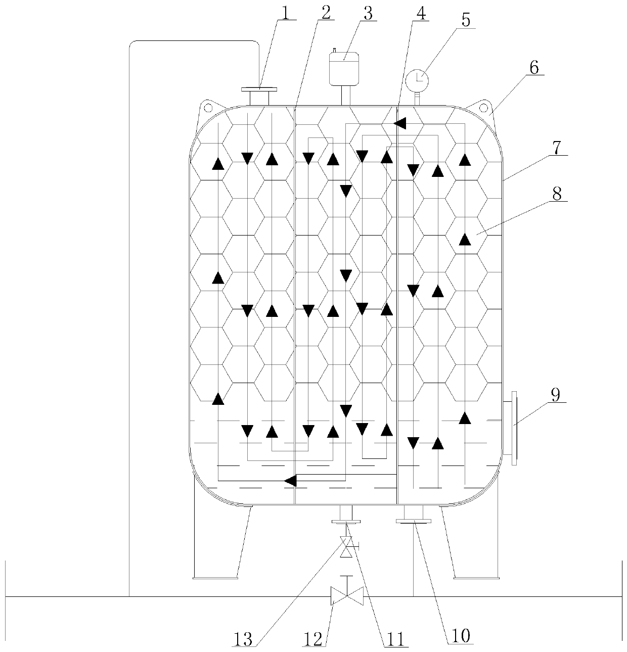
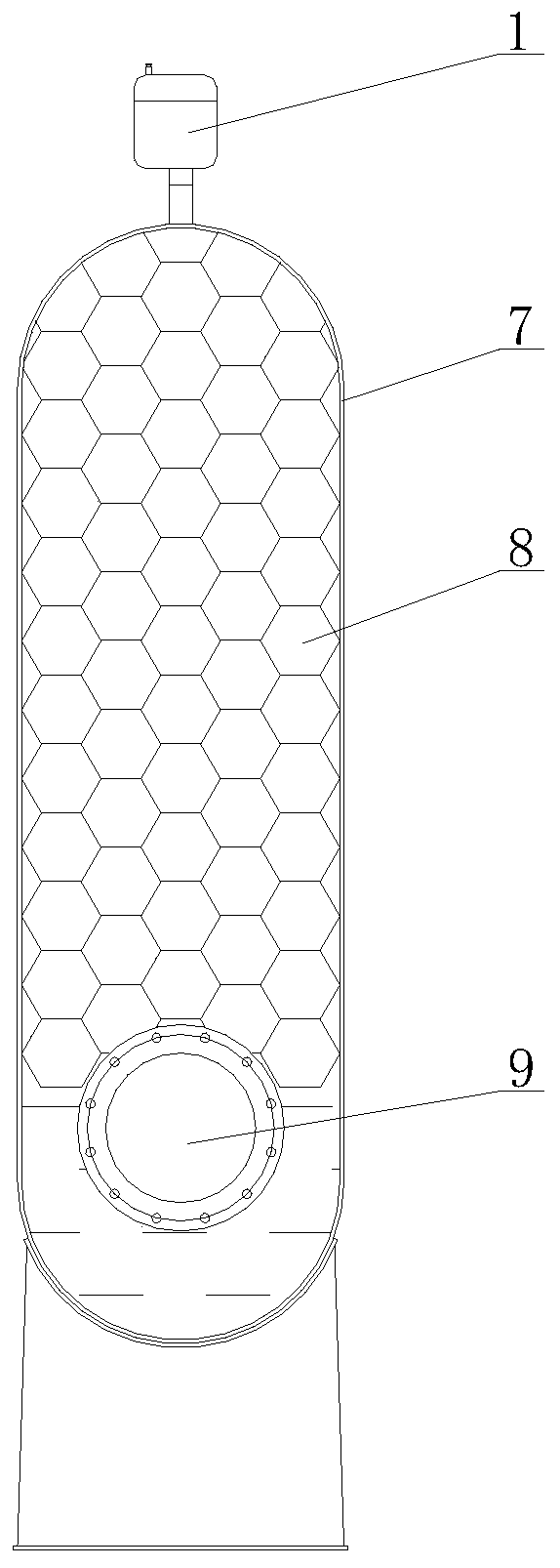
[0019] Such as Figure 1~4 As shown, the isotonic constant pressure compensator of this embodiment is composed of the second inlet and outlet pipe 1, left baffle 2, exhaust pipe 3, right baffle 4, pressure gauge 5, lifting lug 6, expansion tank 7, isotonic expansion Ball 8, filling isotonic expansion ball inlet 9, the first water inlet and outlet pipe 10, sewage outlet 11, drainage valve 12, sewage valve 13, and connection form.

[0020] An exhaust pipe 3 and a pressure gauge 5 are installed on the top of the expansion tank 7. The inside of the expansion tank 7 is subjected to flexible anti-corrosion treatment such as plastic spraying. The inner surface of the expansion tank 7 is not easily oxidized. Lifting lugs 6 are installed on both sides of the top of the expansion tank 7 . One side of the expansion tank 7 is installed with an isotonic expansion ball inlet 9, which is used for filling the isotonic expansion ball 8 and personnel inspection. The left baffle plate 2 is inst...

Embodiment 2

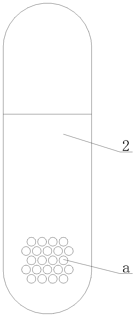
[0022] An exhaust pipe 3 and a pressure gauge 5 are installed on the top of the expansion tank 7 , and lifting lugs 6 are installed on both sides of the top of the expansion tank 7 . One side of expansion tank 7 is equipped with filling isotonic expansion ball inlet 9, left baffle plate 2 is installed on the left side of expansion tank 7, right baffle plate 4 is installed on the right side, left baffle plate 2, right baffle plate 4 will expand tank 7 It is divided into the left area of ​​the expansion tank, the middle area of ​​the expansion tank, and the right area of ​​the expansion tank. The bottom of the left baffle 2 is processed with a diversion hole a, and the upper part of the right baffle 4 is processed with a diversion hole a. The diameter of the diversion hole a is 50mm. The arrangement order of the diversion holes a processed on the left baffle 2 and the right baffle 4 is: the diameters of the diversion holes a are the same, and a row of diversion holes a is alterna...

Embodiment 3

[0025] An exhaust pipe 3 and a pressure gauge 5 are installed on the top of the expansion tank 7 , and lifting lugs 6 are installed on both sides of the top of the expansion tank 7 . One side of expansion tank 7 is equipped with filling isotonic expansion ball inlet 9, left baffle plate 2 is installed on the left side of expansion tank 7, right baffle plate 4 is installed on the right side, left baffle plate 2, right baffle plate 4 will expand tank 7 It is divided into the left area of ​​the expansion tank, the middle area of ​​the expansion tank, and the right area of ​​the expansion tank. The bottom of the left baffle 2 is processed with a diversion hole a, and the upper part of the right baffle 4 is processed with a diversion hole a. The diameter of the diversion hole a is 130mm. The arrangement order of the diversion holes a processed on the left baffle 2 and the right baffle 4 is: the diameters of the diversion holes a are the same, and a row of diversion holes a is altern...


PUM


Abstract

The invention discloses an isotonic constant-pressure compensator. An exhaust pipeline and a pressure meter are arranged on the upper portion of an expansion tank. An isotonic expansion ball filling inlet is arranged on the right side of the expansion tank. Lifting lugs are arranged on the two sides of the upper portion of the expansion tank. A left baffle plate and a right baffle plate used for dividing the expansion tank into an expansion tank left area, an expansion tank middle area and an expansion tank right area are arranged in the expansion tank. Flow guide holes are machined in the bottom of the left baffle plate and the upper portion of the right baffle plate. Isotonic expansion balls extruding one another are arranged in the expansion tank left area, the expansion tank middle area and the expansion tank right area and are filled with gas. A first water inlet and outlet pipe communicating with a pipeline is arranged at the bottom of the expansion tank right area. A second water inlet and outlet pipe communicating with the pipeline is arranged on the upper portion of the expansion tank left area. A water drain valve is arranged on the pipeline. A drain outlet is arranged inthe middle of the bottom of the expansion tank and communicates with a pollution discharge valve through the pipeline. The pressure of the isotonic constant-pressure compensator can be stable, and the phenomena of water hammers and air hammers of the isotonic constant-pressure compensator can be eliminated. The isotonic constant-pressure compensator has the advantages of being convenient to maintain, low in maintenance cost and the like.

Description

technical field [0001] The invention belongs to the technical field of constant-pressure and stable-pressure expansion equipment, and in particular relates to an isotonic constant-pressure compensator. Background technique [0002] The existing pressure-stabilizing expansion equipment is used in thermal power, domestic water supply, fire-fighting systems, agricultural irrigation, industrial pipe networks, etc. The structure of the pressure-stabilizing expansion equipment adopts a diaphragm-type floor-standing expansion water tank and a diaphragm-type air pressure tank. On the main pipe, the pressure-stabilizing expansion equipment can also be installed at the outlet of fluid power lifting devices such as water pumps, air pumps, and compressors to stabilize the pressure. The existing pressure-stabilizing expansion equipment mainly has the following disadvantages: the existing equipment uses carbon steel tanks to hold nitrogen, and air bags and diaphragms to hold water. Since ...

Claims


Application Information

Patent Timeline
Patent Type & Authority Applications(China)
IPC IPC(8): F17D3/01E03B11/08
CPCE03B11/08F17D3/01
Inventor 冉昭杰
Owner 西安华广电站锅炉有限公司
Why Eureka
Try Eureka