Electric melting magnesium furnace shell cooling device and method

A technology of cooling device and fused magnesia furnace, which is applied to furnace cooling devices, furnaces, furnace components, etc., can solve the problems of no unitized structure, unfavorable application and promotion, inconvenient installation and maintenance, etc., so as to reduce the welding workload, The effect of avoiding the risk of passing through the furnace and having good operating conditions

Pending Publication Date: 2020-02-07
ACRE COKING & REFRACTORY ENG CONSULTING CORP DALIAN MCC
View PDF1 Cites 2 Cited by
  • Summary
  • Abstract
  • Description
  • Claims
  • Application Information

AI Technical Summary

Problems solved by technology

However, since the waterway is formed by direct welding of semi-circular pipes or channel steel and the furnace shell, it is easy to have leaks, which greatly increases the probability of waterway leakage, and once the waterway leaks, it can only be shut down for maintenance.
At the same time, the cooling pipe is closed when it meets the longitudinal weld of the furnace shell or the transverse weld of the furnace shell, and is connected with the closed cooling pipe on the other side of the longitudinal weld of the furnace shell or the transverse weld of the furnace shell through the bridge pipe, and the structure is relatively random , without forming a unitized structure, installation and maintenance are very inconvenient, which is not conducive to application promotion

Method used


Image

  • Electric melting magnesium furnace shell cooling device and method
  • Electric melting magnesium furnace shell cooling device and method
  • Electric melting magnesium furnace shell cooling device and method

Examples


Embodiment Construction

[0037] The specific embodiments of the present invention will be further described below in conjunction with the drawings:

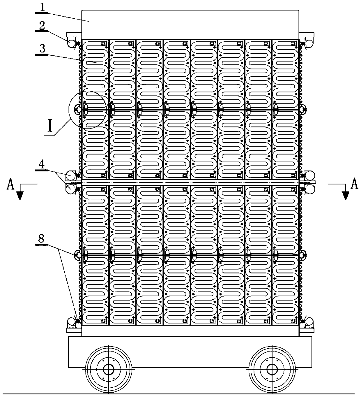
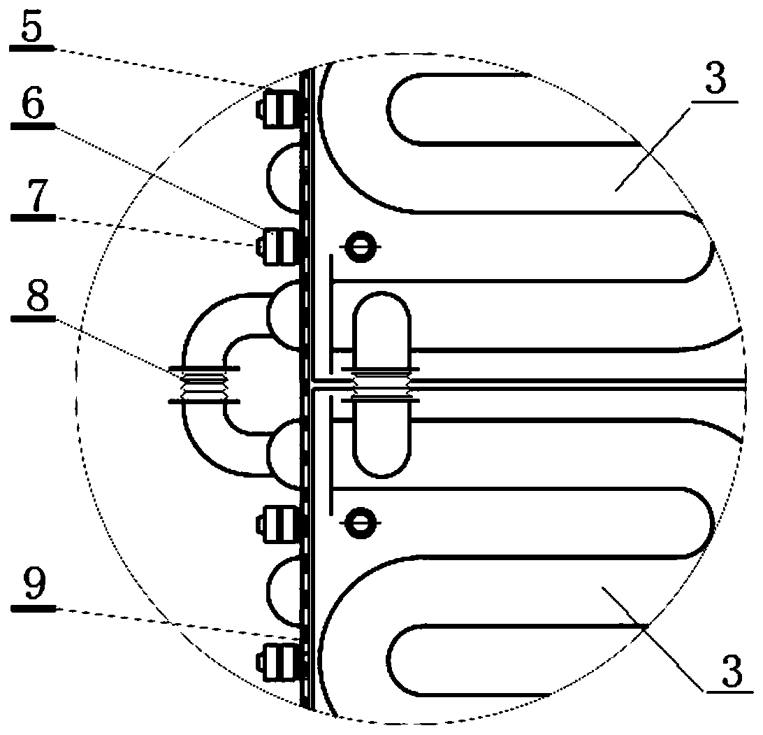
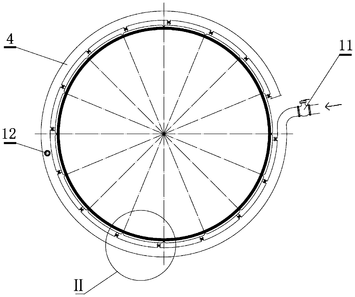
[0038] Such as Figure 1-Figure 3 As shown, the fused magnesium furnace shell cooling device of the present invention includes an upper furnace shell cooling device and a lower furnace shell cooling device. The upper furnace shell cooling device and the lower furnace shell cooling device are respectively composed of a plurality of independent cooling devices. Each cooling unit 3 is connected to the water inlet main pipe 4 through the corresponding water inlet branch pipe 10, and the water outlet main pipe 2 is connected through the corresponding water outlet branch pipe 13; the cooling unit 3 is connected with a plurality of bolts welded on the furnace shell 1. 7 is connected and fixed by a nut 6 and a disc spring 5, and a flexible thermal pad 9 is filled between the cooling unit 3 and the furnace shell 1; the water inlet main pipe 4 and the outlet main pip...


PUM

PropertyMeasurementUnit
areaaaaaaaaaaa

Abstract

The invention relates to an electric melting magnesium furnace shell cooling device and method. The device comprises an upper furnace shell cooling device and a lower furnace shell cooling device. Theupper furnace shell cooling device and the lower furnace shell cooling device are respectively composed of a plurality of independent cooling units. Each cooling unit is connected with a water inletmain pipe through a corresponding water inlet branch pipe, and is connected with a water outlet pipe through a corresponding water outlet branch pipe. The cooling units are fixedly connected with a plurality of bolts welded to a furnace shell through nuts and disc-shaped springs. Spaces between the cooling units and the furnace shell are filled with flexible heat conduction pads. The device is composed of the plurality of cooling units with a unified structure, and the cooling units and the furnace shell are detachably connected, so that not only can the furnace shell be effectively protected,but also the mounting and maintenance are very convenient; and the upper furnace shell cooling device and the lower furnace shell cooling device are put into operation at different phases according to the temperature rise characteristic in the electric melting magnesium production process, so that energy is saved, and synergistic effects are realized.

Description

Technical field [0001] The invention relates to the technical field of fused magnesium production, in particular to an fused magnesium furnace shell cooling device and method. Background technique [0002] The melting point of magnesium oxide is as high as 2800°C, and the melting temperature is above 3000°C when produced by the electric melting process. Therefore, the furnace shell of the fused magnesium furnace (made of 10-16mm thick steel plate) is generally not lined with refractory materials, but is filled with raw materials at the bottom and around as a protective layer. This part of the raw materials needs to be recycled after the fused magnesia melts crystallization and cools down. Treatment, or a small part of it is converted into by-product leather sand, which not only increases power consumption, but also increases the labor intensity of workers and deteriorates the production environment. If the filling amount of this part of the raw materials is reduced, the furnace ...

Claims


Application Information

Patent Timeline
Patent Type & Authority Applications(China)
IPC IPC(8): F27D1/12F27D17/00F24H1/00
CPCF24H1/00F27D1/12F27D17/004Y02P10/25
Inventor 刘杰李超姚苏哲洪艳萍
Owner ACRE COKING & REFRACTORY ENG CONSULTING CORP DALIAN MCC
Why Eureka
Try Eureka