
Connector with testable plugging distance and plugging distance testing method

A technology of connector plugs and connector sockets, which is used in electrical connection testing, parts of connection devices, connections, etc., can solve the problem of incomplete insertion, large connector locking force, and no plug and socket insertion distance. Detection and other problems to achieve the effect of eliminating the influence and eliminating the in-place insertion

Active Publication Date: 2020-02-07
CHINA AVIATION OPTICAL-ELECTRICAL TECH CO LTD
View PDF9 Cites 3 Cited by
  • Summary
  • Abstract
  • Description
  • Claims
  • Application Information

AI Technical Summary

Problems solved by technology

[0003] 1. Due to the design and manufacturing error of the chassis, the connector cannot be mated in place or the mating force is too large;
[0004] 2. The locking force of the connector is large, so that the mating is not in place, such as a threaded or snap-in circular connector with a large shell size;
[0005] 3. The tail of the connector drags a very thick cable, causing the connector to be mated and deflected;
[0006] 4. As an integrated connector for the interconnection interface between devices, it is also prone to mating deflection in the process of blind mating
Existing connectors do not have the function of detecting the mating distance of plugs and sockets, so it is necessary to design a detection structure for the mating distance of plugs and sockets in the connector so that it has the function of detecting the mating distance between plugs and sockets

Method used


Image

  • Connector with testable plugging distance and plugging distance testing method
  • Connector with testable plugging distance and plugging distance testing method
  • Connector with testable plugging distance and plugging distance testing method

Examples


Embodiment 1

[0056] The test method of the mating distance of the connector comprises the following steps:

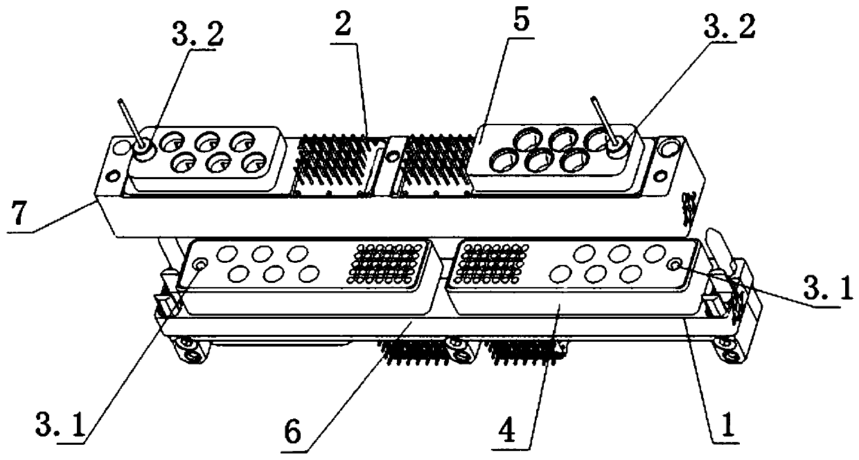
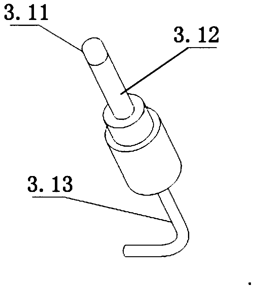
[0057] S1: After the connector plug 1 is mated with the connector socket 2, the same voltage is applied to the two sets of capacitive displacement sensors 3, so that the two sets of capacitive displacement sensors 3 are respectively charged; in this embodiment, the pin terminal 3.1 is grounded, The jack terminal 3.2 has a positive charge.

[0058] S2: Detect the capacitances on the two sets of capacitive displacement sensors 3 through the detection circuit on the device side, and obtain the capacitance values ​​C1=0.91pF and C2=0.93pF;

[0059] S3: According to the calculation formula of pinhole capacitance:

[0060] Calculate the displacement X1=6mm and X2=6mm of the pin terminal 3.1 in the socket terminal 3.2;

[0061] In the formula: the outer diameter of pin terminal 3.1 is d, d=1.9mm

[0062] The outer diameter of jack terminal 3.2 is D; D=2mm

[0063] The dielectric cons...

Embodiment 2

[0069] The test method of the mating distance of the connector comprises the following steps:

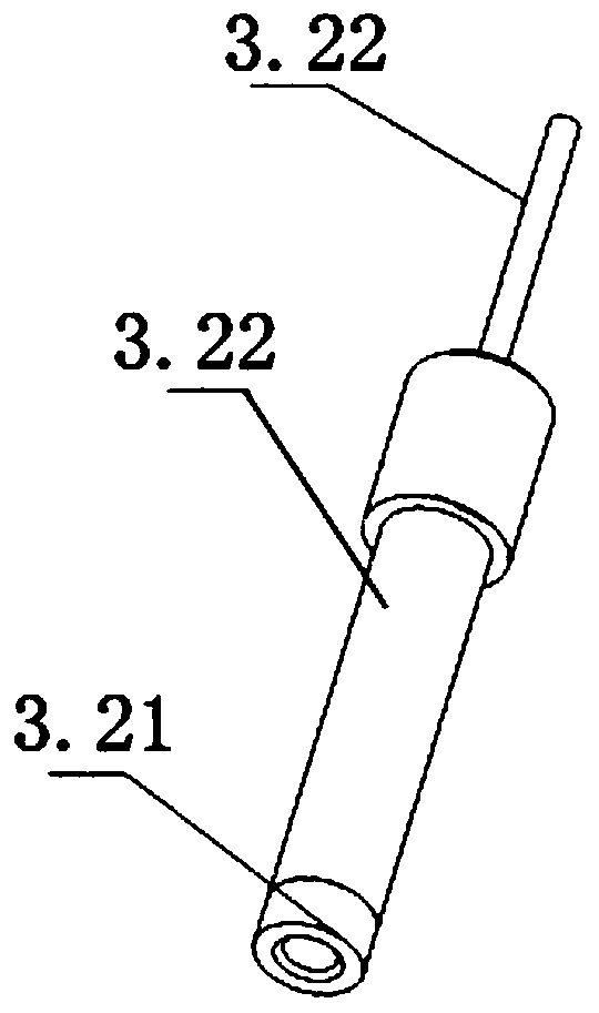
[0070] S1: After the connector plug 1 is mated with the connector socket 2, the same voltage is applied to the two sets of capacitive displacement sensors 3, so that the two sets of capacitive displacement sensors 3 are respectively charged; in this embodiment, the jack terminal 3.2 is grounded, Pin terminal 3.1 is positively charged.

[0071] S2: Detect the capacitances on the two groups of capacitive displacement sensors 3 respectively through the detection circuit on the device side, and obtain the capacitance values ​​C1=0.93pF, C2=1.22pF;

[0072] S3: According to the calculation formula of pinhole capacitance:

[0073] Calculate the displacement X1=6mm and X2=8mm of the pin terminal 3.1 in the socket terminal 3.2;

[0074] In the formula: the outer diameter of pin terminal 3.1 is d, d=1.9mm

[0075] The outer diameter of jack terminal 3.2 is D; D=2mm

[0076] The dielect...


PUM


Abstract

A connector with a testable plugging distance comprises a connector plug and a connector socket. One or more groups of capacitive displacement sensors are correspondingly arranged on the connector plug and the connector socket, and each capacitive displacement sensor comprises a pin terminal and a jack terminal. When the connector is plugged, pin insulating heads are in sliding contact with jack electrodes, and jack insulating sleeves are in sliding contact with pin electrodes, so that the pin electrodes are not in electrical contact with the jack electrodes, and radial gaps are formed betweenthe pin electrodes and the jack electrodes. The invention further discloses a plugging distance testing method, which is used for testing the plugging distance of the connector and judging whether the plugging distance of the connector is in a set range or not. According to the invention, the plugging distance of the connector is tested and whether the plugging distance of the connector is in theset range or not is judged through the capacitive displacement sensors and a detection circuit at an equipment end, so that the problems of working failure of the equipment, damage to the connector and possible potential quality hazards due to the fact that the connector is not plugged in place or is plugged obliquely are solved, and the connection reliability of the connector can be distinguished conveniently during equipment overhaul.

Description

technical field [0001] The invention relates to the technical field of connectors, in particular to a connector with a measurable mating distance and a testing method for the mating distance. Background technique [0002] The connector is an electromechanical component that can realize signal disconnection and conduction. If the mating is not in place, the signal will be blocked and the device will not work normally; if the mating force between the plug and the socket is too large, the use of the connector will be reduced. life, or even damage the connector. As a device interface connector, it often has the characteristics of large volume, many types of transmission signals, many cores, and blind plugging. This kind of connector often has the following problems during use: [0003] 1. Due to the design and manufacturing error of the chassis, the connector cannot be mated in place or the mating force is too large; [0004] 2. The locking force of the connector is large, so ...

Claims


Application Information

Patent Timeline
Patent Type & Authority Applications(China)
IPC IPC(8): H01R13/66H01R24/00G01B7/02G01B21/02G01R31/68
CPCG01B7/02G01B21/02H01R13/6683H01R24/00
Inventor 张小虎陈宏光张磊张东波尤宗毅
Owner CHINA AVIATION OPTICAL-ELECTRICAL TECH CO LTD
Learn More