Combined-type self-sealing structure for deep sea cable cabin-penetrating

A self-sealing structure, deep-sea cable technology, applied in electrical components and other directions, can solve the problems of axial sliding of cables, inability to withstand high voltage, and inability to ensure safety and reliability, and achieve strong applicability, high-voltage reliable self-sealing, high-voltage reliable resistance. Effect of Compression Sliding Ability

Active Publication Date: 2020-02-07
武汉线谱减振科技有限责任公司
View PDF9 Cites 3 Cited by
  • Summary
  • Abstract
  • Description
  • Claims
  • Application Information

AI Technical Summary

Problems solved by technology

But its typical problems are: it is generally unable to withstand high pressure, and cannot guarantee the safety and reliability required by ships and ocean engineering for long-term use.
Among them, although the sealing performance of the filler filling type sealing technology is relatively good, it is not conducive to the maintenance and replacement of the cable; the modular type and the packing winding extrusion type sealing technology are both compressed by the compression system, because the cable is not really rigid. body, the sealing material is also an elastic body, the locking of the cable cannot be achieved, and the cable will slide axially under the high-pressure environment, which will affect the sealing performance of the system
[0006] In addition, in special environments such as deep-sea engineering, it is generally necessary to use cable penetrating sealing devices suitable for depths of more than 6,000 meters. After repeated investigations and demonstrations, there are currently no related products in China that meet the requirements for use, and they need to be imported from developed countries. Technically restricted by developed countries

Method used


Image

  • Combined-type self-sealing structure for deep sea cable cabin-penetrating
  • Combined-type self-sealing structure for deep sea cable cabin-penetrating
  • Combined-type self-sealing structure for deep sea cable cabin-penetrating

Examples


Embodiment Construction

[0030] In order to make the technical means, creative features, goals and effects achieved by the present invention easy to understand, the following will further explain how the present invention is implemented in conjunction with the accompanying drawings and specific implementation methods.

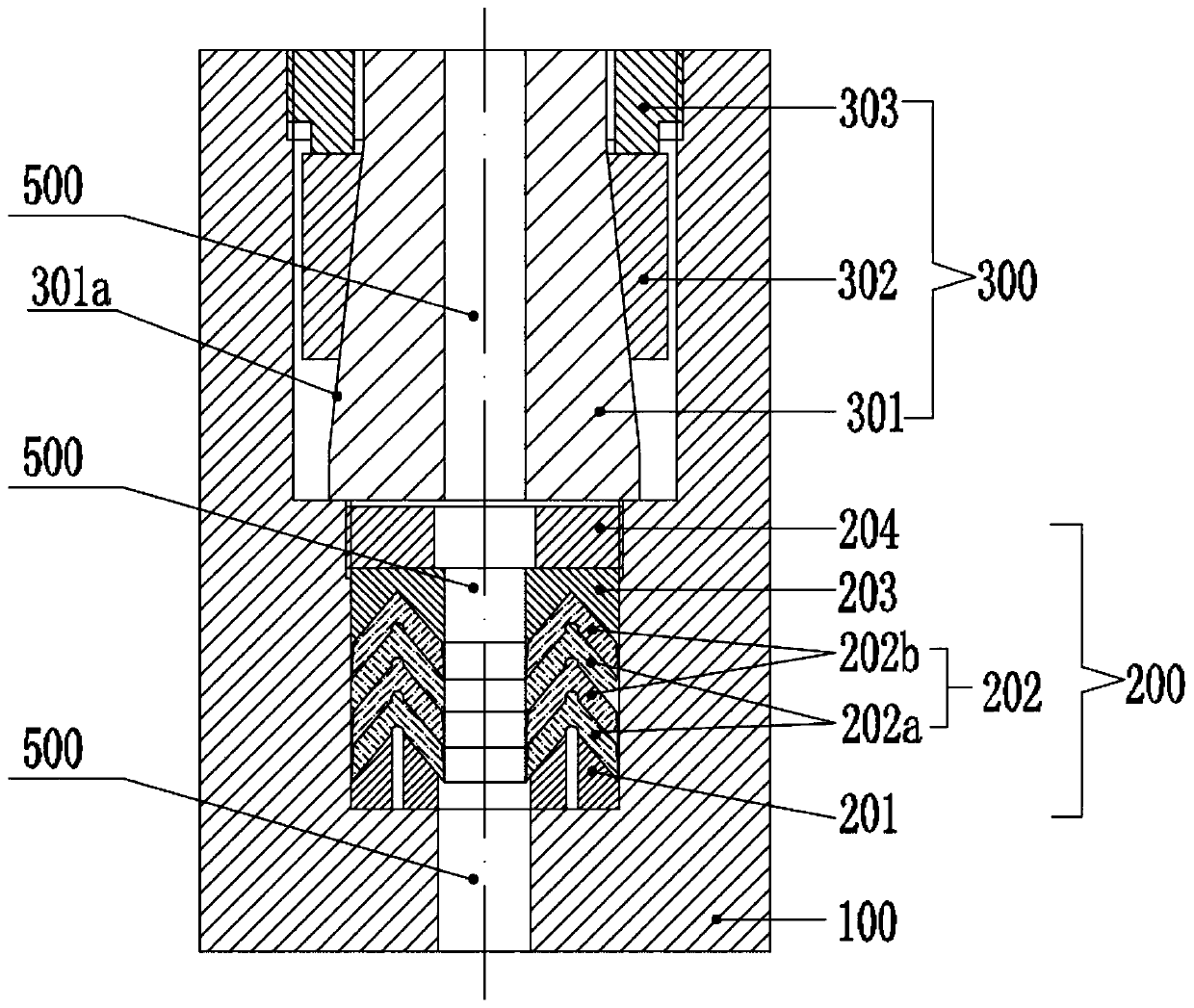
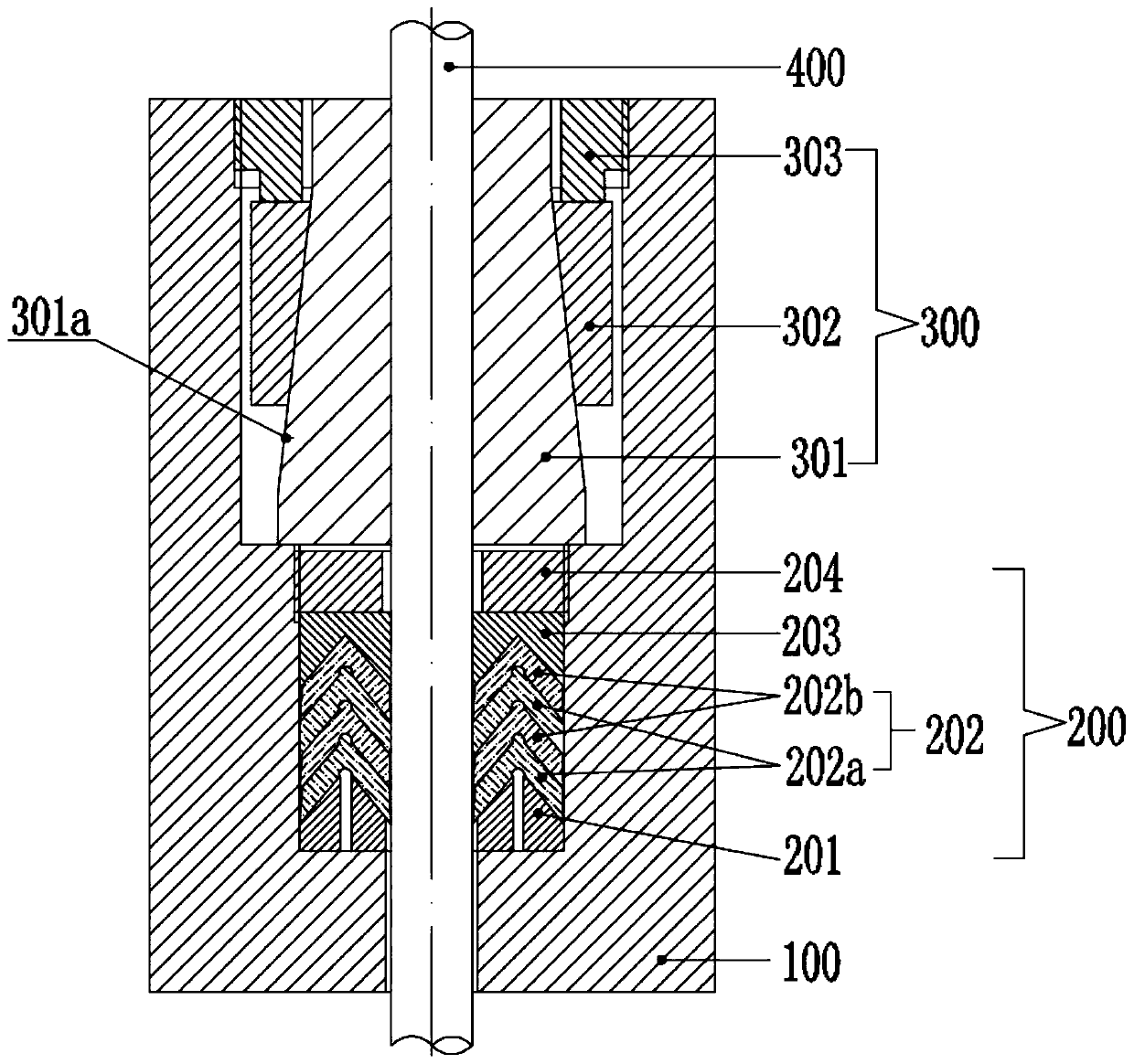
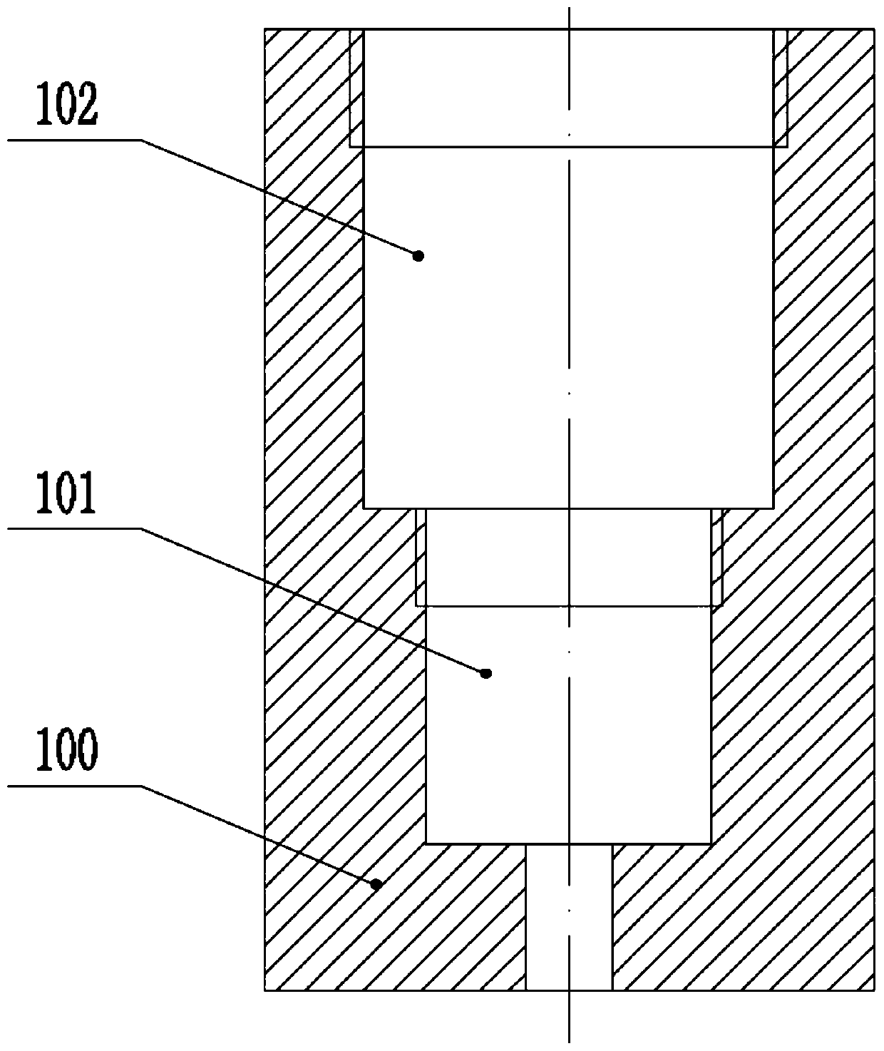
[0031] refer to Figure 1 to Figure 3 As shown, the present invention provides a deep-sea cable penetration combined self-sealing structure, including a packing cavity 100, a sealing and locking structure 200 and a locking and anti-slip structure 300, wherein the sealing and locking structure 200 is embedded in the packing cavity 100 In the provided sealing and locking cavity 101, the locking anti-slip structure 300 is embedded in the locking and anti-slip cavity 102 provided in the stuffing cavity 100, and the sealing and locking cavity 101 communicates with the locking and anti-slip cavity 102, wherein the stuffing cavity 100 is embedded One end with the sealing and locking structure...


PUM


Abstract

The invention discloses a combined-type self-sealing structure for deep sea cable cabin-penetrating. The self-sealing structure comprises a filler cavity, a sealing locking structure and a locking anti-skid structure, wherein the sealing locking structure and the locking anti-skid structure are both embedded in the filler cavity; and the end, embedded with the sealing locking structure, of the filler cavity is a wet end of the combined-type self-sealing structure. The self-sealing structure adopts a special skill of combining high-efficiency self-sealing and cable locking skid-preventing techniques, skillfully utilizes the interaction stress principle of the inclined planes, and makes a split-type locking anti-skid pair generate radial acting force through the interaction between a constraint pair and the split-type locking anti-skid pair under the acting force of a locking nut, so that the purpose of locking the cable is achieved; the self-sealing structure has good sealing performance and cable sliding resistance, has long service life and safety and reliability, and can be used for cable cabin-penetrating sealing in a deep sea environment of 6000 meters or above.

Description

technical field [0001] The invention relates to a cable penetration sealing structure, in particular to a deep-sea cable penetration combined self-sealing structure, which is suitable for the penetration sealing requirements of cables and pipelines of all specifications above Ф10. Background technique [0002] In industrial fields such as ships and oceans, it is usually necessary to use a large number of cable penetration sealing devices. The cable penetration seal is a technical problem that has been difficult to solve for a long time in the design of ships, ocean engineering, especially deep sea engineering. When the cylindrical cable passes through the cabin or deck, due to the irregular diameter of the cable, the non-rigidity of the body, and creep, the common sealing method cannot guarantee the reliability of the seal, and it is prone to water leakage after long-term use. The consequences caused by the short circuit of the circuit are incalculable. In the light case, t...

Claims


Application Information

Patent Timeline
Patent Type & Authority Applications(China)
IPC IPC(8): H02G3/22
CPCH02G3/22
Inventor 周炜望镓绮夏锐
Owner 武汉线谱减振科技有限责任公司
Why Eureka
Try Eureka