
Axial-integrated oil-immersed brushless DC motor position sensor installation structure

A technology for DC motors and mounting structures, applied in the direction of electromechanical devices, structural connections, electric components, etc., can solve the problem of reduced reliability of the Hall position sensor 10 and PCB board 9, failure of the Hall position sensor 10, and attachment to the Hall position Sensors and other issues, to achieve the effect of improving reliability and maintainability, light weight, and small size

Active Publication Date: 2021-08-17
BEIJING SHUGUANG AERO ELECTRICAL
View PDF0 Cites 0 Cited by
  • Summary
  • Abstract
  • Description
  • Claims
  • Application Information

AI Technical Summary

Problems solved by technology

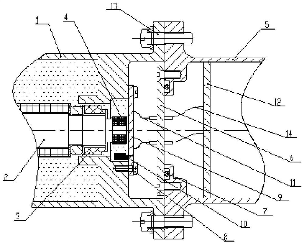
[0004] The Hall position sensor 10 needs to be installed on the PCB board 9 and fixed on the periphery of the rotor position magnetic ring 4. The sensing surface of the Hall position sensor 10 is opposite to the magnetic ring. Then weld the other side of the sealed socket 6 to other circuit boards 12 of the controller by welding the wire 14. For the oil-immersed brushless DC motor, since the inside of the controller cannot be immersed in oil, the position signal needs to be introduced into the controller by installing the sealed socket 6 , the size and weight of the motor will increase
The Hall position sensor 10 and the PCB board 9 are in an oil-immersed state, which will reduce the reliability of the Hall position sensor 10 and the PCB board 9. At the same time, the pollutants in the oil will adhere to the Hall position sensor 10 and the PCB board 9, which will cause long-term damage. The hidden danger of causing the Hall position sensor 10 to fail or the insulation of the PCB board 9 to decrease

Method used


Image

  • Axial-integrated oil-immersed brushless DC motor position sensor installation structure
  • Axial-integrated oil-immersed brushless DC motor position sensor installation structure
  • Axial-integrated oil-immersed brushless DC motor position sensor installation structure

Examples


Embodiment Construction

[0025] In order to make the purpose, technical solutions and advantages of the embodiments of the present invention more clear, the technical solutions in the embodiments of the present invention will be clearly and completely described below in conjunction with the drawings in the embodiments of the present invention. Apparently, the described embodiments are some, not all, embodiments of the present invention. Based on the embodiments of the present invention, all other embodiments obtained by persons of ordinary skill in the art without making creative efforts belong to the protection scope of the present invention.

[0026] The features of various aspects of the embodiments of the present invention will be described in detail below. In the following detailed description, numerous specific details are set forth in order to provide a thorough understanding of the present invention. It will be apparent, however, to one skilled in the art that the present invention may be pra...


PUM


Abstract

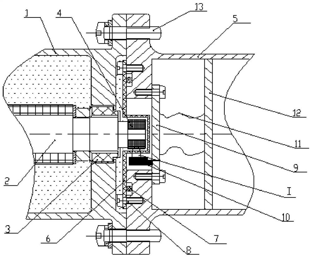
The invention belongs to the technical field of brushless DC motors, and relates to an axially integrated oil-immersed brushless DC motor position sensor installation structure, wherein a Hall PCB board (9) and a Hall position sensor (10) are installed inside a controller, And a Hall seal cover (6) for the mechanical seal controller is installed at the connection position between the motor body shell (1) and the controller shell (5). The Hall seal cover (6) is generally circular, and the middle part It has a circular protrusion, and the internal space of the circular protrusion is matched with the rotor position magnetic ring (4), and the material is magnetically conductive metal; the Hall seal cover structure of the present invention can realize the mechanical connection between the controller and the motor body. Sealed, the Hall sensor can sense the magnetic pole of the magnetic ring to achieve position detection, the motor can remove the sealed connection, the Hall seal cover is small in size, thin in thickness, light in weight, easy to disassemble, improves reliability and maintainability, and can be widely used for various motors.

Description

technical field [0001] The invention belongs to the technical field of brushless direct current motors, and relates to an axially integrated oil-immersed brushless direct current motor position sensor installation structure. Background technique [0002] Brushless DC motors have the advantages of high reliability, good speed regulation, and low loss, and have broad application prospects in the fields of automobiles, aerospace, and ships. The brushless DC motor is composed of a motor body and a controller. The axially integrated brushless DC motor is designed as an axially integrated structure of the motor body and the controller. The integrated oil-immersed brushless DC motor is mainly used for aviation and automotive fuel. The pump system drives the pump to rotate to supply or deliver oil to the engine. The oil-immersed work of the motor can reduce the sealing device of the system, improve the reliability of the system and reduce the regular maintenance. [0003] Usually, ...

Claims


Application Information

Patent Timeline
Patent Type & Authority Patents(China)
IPC IPC(8): H02K11/215H02K29/08H02P6/16
CPCH02K29/08H02P6/16H02K11/215
Inventor 赵雅周罗焱雯李洋
Owner BEIJING SHUGUANG AERO ELECTRICAL
Learn More