
Copper or copper alloy lath and reciprocating coil and method of making the same

A manufacturing method and technology of copper alloy, applied in the direction of metal rolling, metal material coating process, coating, etc., can solve problems such as scars, and achieve the effect of inhibiting the generation of metal powder and reducing bad conditions

Active Publication Date: 2022-07-19
JX NIPPON MINING & METALS CORP
View PDF7 Cites 0 Cited by
  • Summary
  • Abstract
  • Description
  • Claims
  • Application Information

AI Technical Summary

Problems solved by technology

Therefore, compared with the pancake-shaped coil, the reciprocating winding coil tends to produce scratches (scratches) caused by rubbing against each other when micro-vibration is applied for a long time.

Method used


Image

  • Copper or copper alloy lath and reciprocating coil and method of making the same

Examples


Embodiment

[0040] Examples of the present invention are shown below, but the examples are provided for better understanding of the present invention and its advantages, and are not intended to limit the invention.

[0041] (Example, Comparative Example)

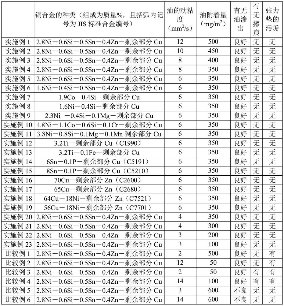
[0042] A reflow tinned copper alloy strip with a width of 20 mm and a thickness of 0.2 mm was coated with lubricating oil (hydrocarbon-based) of the kinematic viscosity and amount shown in Table 1, wound into a reciprocating coil, wrapped with rust-proof paper, and used on rails. It is transported over a distance of 300 km, and then returns to the factory where the reciprocating coil is produced by the same route. After a period of 7 days from the date of return, check whether oil seeps out from the reciprocating coil in the workshop, rewind the reciprocating coil, check whether the reflowed tin-plated copper alloy strip has scratches, and check whether the reflowed tin-plated copper alloy strip has scratches, and is used and tensioned....


PUM


Abstract

The present invention provides a reciprocating coil of copper or copper alloy lath that is unlikely to generate metal powder due to friction with a tension pad, and a manufacturing method thereof. The present invention is a copper or copper alloy strip, the surface of which is coated with a kinematic viscosity of 3-12 mm 2 / s of oil, and the amount of the above oil is 100-500 mg / m 2 .

Description

technical field [0001] The present invention relates to a copper or copper alloy strip and reciprocating coil (トラバースコイル) and a method for producing the same, in particular to a copper or copper alloy strip whose surface is subjected to plating treatment and the reciprocating coil obtained by coiling the same. its manufacturing method. Background technique [0002] In the present invention, copper and copper alloy strips used for electrical / electronic components such as terminals and connectors are products that have been wound into coil shapes. Among the coils, there are pancake coils and reciprocating coils. The pancake coil is a coil that is wound while keeping the edge surfaces (sections) of the bar on the same plane and overlapping, and the pancake coil has the same width as the bar. On the other hand, the reciprocating coil is a coil formed by winding the strip in a spiral shape on a cylindrical bobbin having a longer width in the width direction, and the width of the...

Claims


Application Information

Patent Timeline
Patent Type & Authority Patents(China)
IPC IPC(8): C23C26/00B21B3/00B21C47/12C25D5/48C25D5/50C25D7/06C22C9/00C22C9/02C22C9/04C22C9/06
CPCC23C26/00C23G5/024C23G5/032B21B3/00B21C47/12C22C9/00C22C9/02C22C9/04C22C9/06C25D5/48C25D5/50C25D7/06B21C47/26C25D5/505C25D7/0614C25D7/0607
Inventor 泉千寻
Owner JX NIPPON MINING & METALS CORP
Learn More