Rotor manufacturing method and rotor manufacturing device

A manufacturing method and rotor technology, which are applied in the field of rotor manufacturing and rotor manufacturing equipment, and can solve the problems of reduced adhesive bond strength and reduced adhesive density, etc.

Active Publication Date: 2021-06-18
AISIN AW CO LTD
View PDF7 Cites 0 Cited by
  • Summary
  • Abstract
  • Description
  • Claims
  • Application Information

AI Technical Summary

Problems solved by technology

In addition, if the adhesive expands excessively, the part where the blowing agent is pushed away by the vaporized solvent remains as a cavity, and the density of the adhesive decreases.
Therefore, there is a problem that the adhesive strength of the adhesive decreases

Method used


Image

  • Rotor manufacturing method and rotor manufacturing device
  • Rotor manufacturing method and rotor manufacturing device
  • Rotor manufacturing method and rotor manufacturing device

Examples


Embodiment Construction

[0027] Hereinafter, embodiments of the present invention will be described with reference to the drawings.

[0028] [Structure of the rotor of the present embodiment]

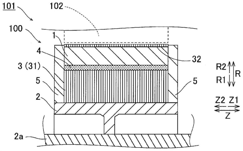
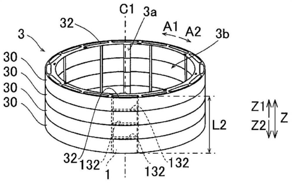
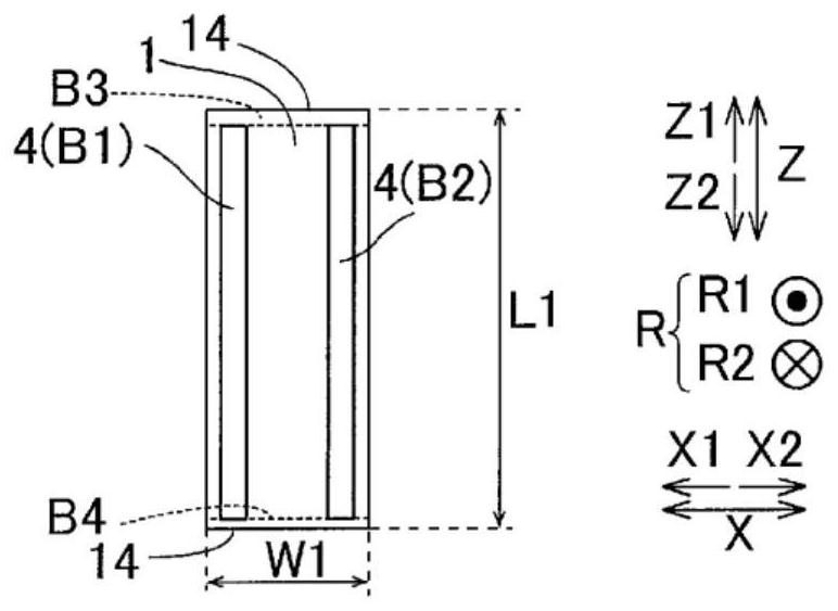
[0029] refer to Figure 1 ~ Figure 15C The structure of the rotor 100 of this embodiment will be described.

[0030] In addition, in the specification of the present application, "rotating electric machine" is described as an overall concept including a motor (electric motor), a generator (generator), and, if necessary, a motor / generator having functions of both a motor and a generator. For example, rotating electrical machine 101 is configured as a running motor used in a hybrid vehicle or an electric vehicle.

[0031] In addition, in the specification of this application, "rotor rotation axis direction" or "axial direction" refers to the rotation axis direction of the rotor 100 (along the axis C1 (refer to figure 2 ) direction; and figure 1 in the direction parallel to the Z-axis). In addition, "circumfer...


PUM


Abstract

The present invention relates to a rotor manufacturing method and a rotor manufacturing device. The method for manufacturing the rotor includes: heating the binder to a temperature in a temperature range between the vaporization start temperature and lower than the expansion start temperature at which the diluent solvent volatilizes; The process of volatilizing the diluent solvent by raising the temperature of the adhesive at a slow temperature rise rate in the temperature range.

Description

technical field [0001] The present invention relates to a rotor manufacturing method and a rotor manufacturing device. Background technique [0002] Conventionally, a rotor manufacturing method is known in which a permanent magnet is inserted into a magnet hole portion of a rotor core. For example, Japanese Patent Application Laid-Open No. 2007-151362 discloses a method of manufacturing such a rotor. [0003] Japanese Patent Application Laid-Open No. 2007-151362 discloses a permanent magnet fixing method in which a permanent magnet is inserted into and accommodated in a storage groove of a rotor core. In this permanent magnet fixing method, first, the molten adhesive is dropped onto the surface of the permanent magnet, whereby an adhesive containing a foaming agent foamed by heating is disposed. Then, in order to cure the adhesive material and reduce the thickness of the adhesive, the adhesive material is heated and pressed with a press. Then, insert the permanent magnet ...

Claims


Application Information

Patent Timeline
Patent Type & Authority Patents(China)
IPC IPC(8): H02K1/27H02K15/02H02K15/03
CPCH02K1/27H02K15/02H02K15/03H02K1/276H02K1/28H02K15/12Y10T29/49012
Inventor 松原哲也郡智基高须明近藤贵雅
Owner AISIN AW CO LTD
Why Eureka
Try Eureka